Continue to Site

Eng-Tips is the largest engineering community on the Internet

Intelligent Work Forums for Engineering Professionals

  • Congratulations KootK on being selected by the Eng-Tips community for having the most helpful posts in the forums last week. Way to Go!

Reinforcing a W section for Torsion. 3

Status
Not open for further replies.

Sweever

Structural
Sep 13, 2017
29
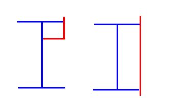
I have an existing W section that is loaded eccentrically, about 5" off the web centreline. There is no way to brace the flanges and take out the torsion and no easy way to remove the beam and replace with a HSS. We were thinking of installing a HSS section in the top right corner of the beam and welding it to the top flange and web of the beam to take the torsion. Anyone ever done this? If the W section can take the bending and shear, can one just design the HSS to take the torsion and provide a suitable connection at the column? Would there be issues with the section no longer being symmetric? Never really have done any torsional reinforcements before and typically stay away for torsional situations. Any comments would be appreciated.

Thanks
 
Replies continue below

Recommended for you

I doubt that would fix it because the bottom flange wouldn't be restrained.

Are there beams framing into points adjacent (i.e. on each side) to where the torsion is applied? I've used that in many cases to take out the torque. It basically goes into the beams as a strong axis moment. (Utilizing the small amount of fixity a shear connection has.)

 
Unfortunately, no beams framing into the side of the beam under torsion and none can be installed due to hopper bins.
 
I don't think the torsion will ever be resolved into the HSS tube unless it engages both the top and bottom flanges. You could weld continuous plates to close the wide flange shape; it may be your best bet.
 
I haven't done it but it sounds like something I would try. The torsional stiffness of the HSS should easily be higher than that of the W section so I can't see it not working as long as local flange/web buckling mechanisms are prevented.
 
I agree with charliealphabravo. If the closed section can resist the torsion, and you can develop that at the end, it works.
 
OP said:
Anyone ever done this?

I have, with an angle instead of a tube. The angle formed a tube with the flange and web.

hokie66 said:
and you can develop that at the end,

I see this as being absolutely critical but, by the sound of it, you're already on top of this.

WARose said:
I doubt that would fix it because the bottom flange wouldn't be restrained.

I see this as also being critical but, at the same time easily resolvable. However the load is delivered, and I'd recommend sharing that with a sketch, you'll need a chain of stuff that takes the load from the point of application over to the tube from a torsional perspective. I'm guessing this is a series of plate elements in bending. That said, once you've check this, you should be good to go. And I suspect that it would work easily.

OP said:
If the W section can take the bending and shear, can one just design the HSS to take the torsion and provide a suitable connection at the column?

This, in addition to the check that I just mentioned, probably is what I'd do.

OP said:
Would there be issues with the section no longer being symmetric?

There would but I wouldn't lose much sleep over it. Thin plate metal sections like this become intractable problem in a hurry under combined actions. Even our traditional ways of combining biaxial bending and torsion are very approximate. Use your best judgement and I'm sure that you'll be fine. At the risk of sounding condescending, I feel that you're saying all the right things here.
 
Just one caveat...the torsion to be resisted should be based on the lever arm between the force and the closed section.
 
my instinct was the same as mike's ... a plate to close the section ... maybe two, one above (for the peaks) and another below (for the troughs).

another day in paradise, or is paradise one day closer ?
 
I like KootK's idea of using an angle to create a box section, or angles on both sides, or even all four corners, depending on how much torsional restraint you need. I doubt an HSS would fit into the corner of a wide flange - the fillets would be too big.
 
The angle idea is a good one. But you have to be sure to close the section: you'd have to connect the legs via some type of weld to have a true closed/tube section. Any gap at all, and it changes the ball game.

 
Sweever said:
Would there be issues with the section no longer being symmetric?

I think this is kind of key to your problem isn't it? If you reinforce the your section on one side only, you're going to change your design eccentricity for the better or worse. If you reinforce strategically, maybe you can reduce the eccentricity all together. Also, I agree with above regarding connections being key for this, from a design and installation point of view.
 
I've generally retrofit in a plate that closes the wide flange by connecting the top and bottom flange near the toes on each side. For smaller loads, a couple of angles to close the top part sound good too. Just make sure you put in some kind of stiffener at the load application point to hold the box section square. [pre][/pre]
 
Thanks for the ideas and comments. We did think about the angle, but it would likely be a lot of welding to get the angle and existing W section to behave as a HSS section. With the HSS in the corner, we believed we may be able to reduce the welding significantly, though only the numbers will tell. The beams are also quite deep W18 and W30, so using a full plate from top flange to bottom flange seemed like a significant expense for the contractor.
 
hokie66 (Structural)22 Oct 18 21:38
Just one caveat...the torsion to be resisted should be based on the lever arm between the force and the closed section.

Yes, I agree, and this reduces arm and the torsion by doing this.
 
OP said:
We did think about the angle, but it would likely be a lot of welding to get the angle and existing W section to behave as a HSS section.

I wouldn't let that be the basis of your decision. You'll likely find that a ridiculously light welding pattern will get the job done by the numbers. It's straight shear over a very long length, right? Another consideration is that you'll need to make your tube large enough that it's torsional stiffness shields the wide flange from absorbing significant torsional strains and stresses. Once you size your tube for that, the weld demand should naturally calc out pretty small.

OP said:
Yes, I agree, and this reduces arm and the torsion by doing this.

Are you sure? I would expect the reverse as far as the combined section is concerned.
 
KootK- I thought I was sure, what am I missing. The shear center/ centroid of the HSS is closer to the load than the web of the beam thereby reducing the moment arm.
 
Is this a crane girder subjected to fatigue? This should play a significant part in deciding what kind of welding will be required. Another issue with matching to an existing beam is trying to get the curvature of one stiff element to match another (jacking an angle into a curved shape would probably be frustrating). A square HSS would probably be simpler and any side plating would need to be cut and spliced to match the curve. A heavy top and bottom plate might wind up as the best choice.
 
why is an angle creating what I visualise is a small closed section preferred to a plate closing the entire W section ? You could close the peaks or the troughs or both. You could add lightening holes if this is a problem; heck, you could make a truss close the section for you.

just ignore me ! W = Wide, not "W" ...
 
OP said:
KootK- I thought I was sure, what am I missing. The shear center/ centroid of the HSS is closer to the load than the web of the beam thereby reducing the moment arm.

It sounds as though you're right. It would be very helpful -- to me at least -- if you could post a rough sketch of the situation and constraints of the problem.

Teguci said:
(jacking an angle into a curved shape would probably be frustrating)

Solutions to that:

1) Install the angle in segments with splice plates at the but joints. Or a through plate.

2) Set things up such that the vertical angle leg is outboard of the beam flange, permitting vertical tolerance. This would need to suit any spatial constraints of course.

c01_wana7k.jpg


rb1957 said:
why is an angle creating what I visualise is a small closed section preferred to a plate closing the entire W section?

I would certainly agree that the plate option is a good one if it's spatially possible.
 
Status
Not open for further replies.

Part and Inventory Search

Sponsor