Eng-Tips is the largest engineering community on the Internet

Intelligent Work Forums for Engineering Professionals

Reinforcing a W section for Torsion. 3

Status
Not open for further replies.

Sweever

Structural
Sep 13, 2017
29
0
0
CA
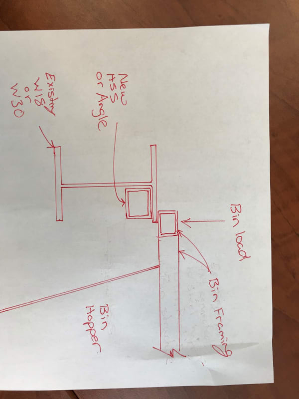
I have an existing W section that is loaded eccentrically, about 5" off the web centreline. There is no way to brace the flanges and take out the torsion and no easy way to remove the beam and replace with a HSS. We were thinking of installing a HSS section in the top right corner of the beam and welding it to the top flange and web of the beam to take the torsion. Anyone ever done this? If the W section can take the bending and shear, can one just design the HSS to take the torsion and provide a suitable connection at the column? Would there be issues with the section no longer being symmetric? Never really have done any torsional reinforcements before and typically stay away for torsional situations. Any comments would be appreciated.

Thanks
 
Replies continue below

Recommended for you

See sketch below.

The bin manufacturer doesn't want any additional load into his bin framing.

The reason I dont want to use plates is the size of the W sections. 18 and 30" deep plates are a significant cost and would be difficult to install. The HSS or Angle is simpler.

IMG_4675_pvzub9.jpg
 
I like the HSS stitched to the wide flange. With the angle or plate solutions I see it as needing continuous welding to maintain the closed section which is gonna suck if this in place and you're grinding paint and welding in tight areas overhead.
 
Thanks. I'd imagined something similar but figured it would be easier to install the new stuff on the opposite side of the web. I don't feel that the plate solution would be cost prohibitive but you obviously know the preferences of your construction team better than I.
 
canwesteng said:
...I see it as needing continuous welding to maintain the closed section...

I disagree and am confident that stitch welding is fine for this. It's not appreciably different from flexural reinforcing for which stitch welding is ubiquitous.
 
Flexural reinforcing carries axial force, and stich welding carrying the longitudinal shear is easy enough to visualize, and simple to sketch out as satisfying equilibrium. I'm not sure how to rationalize that in this case, where the torsion is transverse shear in the section, and the second the close section is cut (or where the welds end) you no longer get a nice loop of transverse shear, as the shear stress needs to be zero at the free ends of the angle.
 
canwest said:
I'm not sure how to rationalize that in this case

I can help with that:

1) take any differential element on any face of the tube and sketch out it's equilibrium state with shear etc.

2) expand the differential element so that it's large enough to encompass at least one stitch weld on the welded sides.

3) reformulate your differential element so that, instead of uniform edge shears, you have discrete weld shears, still maintaining equilibrium.

Voila! Another way to look at it is as an analogy to a 3D space truss. The truss has non-continuous shear transfer but, still, killer torsional properties.

I get that the "closed loop" stuff from mechanics of materials is seductive but it's not the whole story here. At it's heart, it's just a shear flow as it is in the flexural case. That said, things are mechanically weird between welds so I wouldn't go and make the stitching 72" o/c or anything. I think that a spacing not more than twice the angle leg width would make for a reasonable maximum. 2"@8" etc.
 
Hello Combined bending and torsion of a W beam is dealt with in 'Basic steel Design' by Bruce Johnston and others. These calcs and tables make use of the Cw warping constant (per AISCM)and a torsional bend constant 'a'. Normally this book is intimatly tied to the AISC manual, but in this case thier tables are not listed with a AISC ref. It does have examples with 24Ft long beams, but does warn against the increased deflections or angles of twist. The tables give the angles of twist. I have only used it once or twice.

Note that this is a very good book for simply explaining the AISC endless list of inter-twined specs. With flow charts that simplyfy the use of the AISC.
 
I'll repeat my earlier caution with regard to fitting an HSS section into the corner of a W-beam. Fillet radii for W-beams can be up to 3/4", while the HSS outside radii is typically twice the wall thickness. If you're using a fairly heavy HSS section, it may work, but you'd end up with a fairly large gap to weld for a lighter HSS.

The ratio of torsional stability to weight of a box created using an angle should be considerably better than for the HSS.

If the ends of the HSS or angle are supported, that will move the shear center, so it would be advantageous to add the angle or HSS to the side closer to the load in that case. I could be mistaken, but don't believe it matters for torsional stiffness which corner is used to put or create the box section. You could do something similar to what is shown in KootK's left sketch, but put it in the bottom corner, extending past the bottom flange to avoid alignment problems.
 
Koot, I agree but with an asterisk.

A weld discontinuity shifts torsion into bending of individual elements where there's no weld (or field action, as per below). You'll have a significant stiffness drop in those areas and a drop in strength. It's possible to check those conditions, but I wouldn't be doing it without thinking hard.

You can physically try this yourself. Fold a piece of card into a box section and twist it. Now take a knife and cut the corners periodically. You're going to significantly increase flexibility and decrease capacity without load continuity.

Some spacing will obviously be fine. It's likely a plate thickness and member width to weld spacing limit where local effects will bridge the fasteners (i.e. you have something like truss action in a field between the welds, which is basically what you're proposing). The problem is that I don't know what that number is. I'd be comfortable with a pretty stocky section, but would be less comfortable as I got more flimsy. I'd also give a significant safety factor on the strength and keep the gaps small. Once I'm doing that, it's honestly probably faster and cheaper to just lay down a quarter inch weld.

This is well into engineering judgement land, though. I can think of situations where I could land on both sides of this. There's somewhere where load paths will transition and nailing down where that point is is tricky.
 
HotRod10- I envisioned I would have to use maybe a 1/2" thick HSS to make the radius work. Still in the early stages of this idea.

I thought using an HSS would be simpler, and would not be sharing stresses in the top flange of the beam (ie, torsion stress and bending stress). I think the beam is near or at capacity as it is. I understand the weight of the HSS would be more than double than just putting in the angle with not much increase in torsional resistance.

I did not however understand your comment "if the ends of the HSS are supported, that will move the shear centre? Can you elaborate?
 
If I'm not mistaken about the internal mechanics (although I could be mistaken), if only the W-beam is supported at the ends of the beam, then the eccentricity to the load remains from the centerline of the web. Whereas, if the HSS or angle is attached to the support, the shear center would move to, or at least closer to, the centroid of the composite section.
 
You only really need to worry about combination of tension/compression due to bending and shear due to torsion when you're high in the stress ranges. They're operating in different directions and with different effects. The Indian standards, for instance, don't get you to worry about shear/bending interaction in an element until you're using 50% of the shear capacity.

I would agree that you should think about it, but I would hope that your torsional shear stresses are pretty small in these cases.
 
I can't see the small weight savings of the angle factoring in here. If the fillet is a concern, I would add a spacer to the HSS to clear the fillet (welded in the shop of course). I can buy the space truss analogy for torsional stiffness, but it seems awfully complicated to check. Might be justifiable with low loads but supporting a bin I want something with a nice clean load path.
 
Ignore the spacer completely even - just move the HSS away from the web. I don't see why it needs to tuck in so neatly, provide you add some properly detailed stiffeners at the location of the load to transfer torsion to the HSS.
 
canwesteng is correct. For a torsional member to be effective, it needs to be continuous. Cut a side out of the CLOSED section at any point, and the shear has nowhere to go.
 
Wondering if there's any scope to simply move the beam over, sketch seems to look like in terms of the hopper it would work. Depends on a lot of other factors obviously,but it was the first thing that came to mind if the geometry is to scale.
 
I think Sweever has the right approach figured out, but maybe some here don't. There are three crucial concepts in torsion demonstrated in this discussion.

1. Closed sections provide vastly superior torsional performance as compared to open sections.
2. Torsional closed sections need to be closed along the complete length. Most would agree that a flexural cover plate cannot have discontinuities, neither can a torsion bar. Torsion is shear, and the shear resistance cannot be interrupted.
3. Torsional members must be torsionally connected at the supports.
 
Status
Not open for further replies.
Back
Top