Continue to Site

Eng-Tips is the largest engineering community on the Internet

Intelligent Work Forums for Engineering Professionals

  • Congratulations waross on being selected by the Eng-Tips community for having the most helpful posts in the forums last week. Way to Go!

Retaining Wall - Flexural Reinforcement from Stem Into Footing 21

Status
Not open for further replies.

CWEngineer

Civil/Environmental
Jul 3, 2002
269
I am trying to get some clarification regarding the flexural reinforcement of the stem of a retaining wall into the footing.

Does the flexural reinforcement in the stem of a wall, need to be developed into the toe, such as show in Figure 1 of the attached document. Or is providing a standard hook (12db), sufficient, such as that show on Figure 2 of the attached document? If providing a standard hook is sufficient, can the hook be turned towards the heel?

Thanks in advance
 
 http://files.engineering.com/getfile.aspx?folder=8fc7a958-bb23-4694-a010-30dca047d4a9&file=Flexural_Reinforcement.pdf
Replies continue below

Recommended for you

Thanks for all your input, it has been very informative. Just want to clarify my questions and checked if the revised sketches (attached) are acceptable or required per ACI 318-11. The Embedment Depth into the footing and standard hook lenghts are provided per ACI 318.

1). Figure 3: This figure is similar to Figure 14-1 in the CRSI Design Handbook. Is extending the flexural reinforcement from the wall all the way to the end of the toe, required?

2) Figure 4: Is providing a standard hook, which is not spliced to the bottom reinforcement acceptable? The flexural reinforcement has been designed to resist the lateral loads and has the appropriate embedment into the footing.

3) Figure 5: Is providing a standard hook, which is spliced (with appropriate splice length) to the bottom reinforcement acceptable? The flexural reinforcement has been designed to resist the lateral loads and has the appropriate embedment into the footing.

Thanks, really appreciate your feedback and help.
 
 http://files.engineering.com/getfile.aspx?folder=1056cbf8-a4bf-412b-9e5e-511fabb7ac47&file=Rebar_Sketches.pdf
sketch 3 except move the bottom bar to the top of the footing (2" clr) and verify that it is fully developed Ld by the time it gets to the wall reinforcing (hook at the front of the toe otherwise). There is no reason to have a second layer of bottom reinforcement if you extend the hook length to the end of the toe.
 
@CWEngineer: I'm glad that you're back and that all this debate hasn't been for naught! My opinions are indicated below. Obviously, a consensus is unlikely.

CWEngineer said:
1)Figure 3: This figure is similar to Figure 14-1 in the CRSI Design Handbook. Is extending the flexural reinforcement from the wall all the way to the end of the toe, required?

In general yes. However, if you plan to turn the hook towards the toe and lap it with your footing bottom steel, then I would say no.

CWEngineer said:
2) Figure 4: Is providing a standard hook, which is not spliced to the bottom reinforcement acceptable? The flexural reinforcement has been designed to resist the lateral loads and has the appropriate embedment into the footing.

In general no. Not unless the standard hooked bar is somehow also able to satisfy a) the STM requirements discussed above or b) lap with the bottom bars for the tension needing to be transferred.

CWEngineer said:
3) Figure 5: Is providing a standard hook, which is spliced (with appropriate splice length) to the bottom reinforcement acceptable? The flexural reinforcement has been designed to resist the lateral loads and has the appropriate embedment into the footing.

Yes.


I like to debate structural engineering theory -- a lot. If I challenge you on something, know that I'm doing so because I respect your opinion enough to either change it or adopt it.
 
Teguci, I don't know. The Nilsson work was only published in 1973, so perhaps they haven't had time. And I don't think TXStructural works for CRSI anymore.

KootK, about your answer to CWE's Figure 3...I think you mixed up "toe" and "heel". The way he shows it, toward the toe, is correct.

CWE, does any standard hook provide a tension splice length? I thought not.


I'm not switching sides or anything but I am going to make a point that runs contrary to my own opinions in this matter. Per the sketch below, consider:

1) A retaining wall rotated 90 degrees to look like a beam-column joint.

2) Don't sweat the construction joints being the wrong places. All resolvable via direct shear checks.

3) This wouldn't work for "toe-less" walls or short toe walls.

If this were a beam-column joint, I believe that:

1) Most of us would find it satisfactory by inspection.

2) Other than in high seismic zones, I don't believe that checks beyond Ldh would be requied.

Capture_yqhvql.jpg


I like to debate structural engineering theory -- a lot. If I challenge you on something, know that I'm doing so because I respect your opinion enough to either change it or adopt it.
 
hokie said:
KootK, about your answer to CWE's Figure 3...I think you mixed up "toe" and "heel". The way he shows it, toward the toe, is correct

It's not a misprint but I could have said it better. I meant that, should a bar developed to the toe be replaced with another kind of hooked bar, that hook would also need to be turned towards the toe.

I like to debate structural engineering theory -- a lot. If I challenge you on something, know that I'm doing so because I respect your opinion enough to either change it or adopt it.
 
We would accept the beam-column joint because we only want a nominal bending capacity at that location. It is not typically a cantilever...but if it is a cantilever, it should be treated similarly to the retaining wall. I wouldn't consider that clamping enters into it, but then you know my attitude to shear-friction.
 
Good reference, slickdeals. But just turning the bars in only develops "nominal moment strength", according to the caption beside the picture. It is good to see that they referenced the "Research in Sweden many years ago", which I think is the work of Nilsson et.al. which we have been discussing.
 
The explanations given by @Koutk are convincing. However if the footing is too thick compared to the stem, in a way to ensure a full development length, does the moment connection still matter or not?
 
Lak20016 said:
However if the footing is too thick compared to the stem, in a way to ensure a full development length, does the moment connection still matter or not?

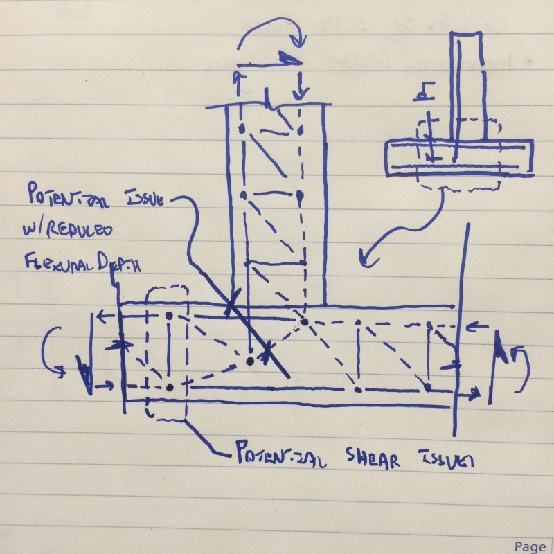
It still needs to be a moment joint but it can take a different form that, while not particularly efficient, may not require the vertical reinforcing to round the corner of the joint. See the strut and tie representation below.

image_t4sxyx.jpg


I like to debate structural engineering theory -- a lot. If I challenge you on something, know that I'm doing so because I respect your opinion enough to either change it or adopt it.
 
koutk said:
See the strut and tie representation below.

If the potential shear issue is well understood, I am still confused about the second potential issue( on the left side of the draft) Could you explane to me more, please?

In the case that we have a shear wall connected to a thick mat, should the vertical reiorcment round the corner or not?
 
lak20016 said:
If the potential shear issue is well understood

I don't think that it's well understood at all. Consider:

1) Just look at the diversity of opinion here.

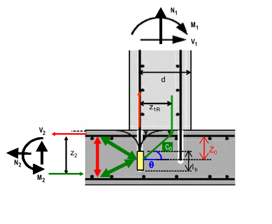
2) I made up my own STM for this and have yet to see another in print other than similar stuff for post-installed rebar (attached).

lak20016 said:
I am still confused about the second potential issue( on the left side of the draft) Could you explane to me more, please?

I'll try:

1) On the left, your effective flexural depth is reduced to correspond to the level of embedment of the wall stem bars. Normal design practice would use the full "d" of the footing.

2) On the left, you have a concrete anchorage situation with regard to the wall stem bar embedment. It kind of depends on how one chooses to look at it but I view it as a sort of shear failure left of the stem that would involve a depth less than the full depth of the footing.

3) At the leftmost node on the bottom, there's a bursting tendency that exacerbates the demand on the "tie" at that location. In most retaining wall designs, the "ties" will be non-existent as rebar. Rather, the ties will represent footing diagonal tension shear (Vc). Thus, ultimately, we hav eanother source of shear issues.

I've attached a few pages from a clever document from Hilti Europe for post installed rebar situations. It covers a lot of the same concepts. I'm hoping that you will find it helpful.

Capture_y1khe8.png


I like to debate structural engineering theory -- a lot. If I challenge you on something, know that I'm doing so because I respect your opinion enough to either change it or adopt it.
 
In addition to the development requirement, ld, ACI 318-11 12.10.3 requires developing the reinforcement at least a distance of "d" past where it is needed. In this case, d is for the wall and effectively requires the wall reinforcement to extend at least about the width of the wall into the footing. Further, if the shear is close to the concrete shear capacity in the footing or slab, then the flexural reinforcement is not allowed to be cut-off in the tension zone (12.10.5).

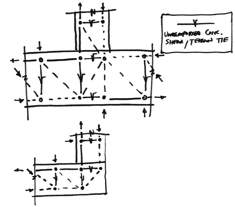
As for the strut tie models, I continue to have problems at the tension tie terminations as well as dealing with the unreinforced, concrete shear/tension ties. With the understanding that a bar being developed transfers its tension into the concrete via shear then something like this can be proposed (and also adds credence to the shear being the limiting factor). Without the shear tension ties, many of the strut tie models above and published in books do not work because the tension terminations are shown way to close to the face of an element to allow for the correct tension development even with a hook.

stm2_corrected_k3b50x.jpg


Update - made shear ties orthogonal and shear struts diagonal.
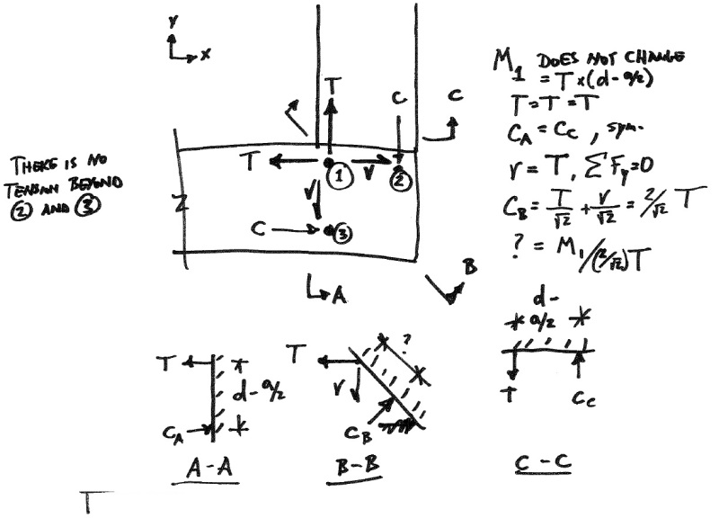
Below is my attempt to show why tension around the bend doesn't exist for the open corner condition. The tension in the reinforcement is effectively 0 when it gets to the hook/bend.
stm_compatibility_mv5xam.jpg
 
lak20016 said:
in the case that we have a shear wall connected to a thick mat, should the vertical reiorcment round the corner or not?

I forgot to respond to this bit of your question. For out of plane wall moment, I would say yes, the rebar generally should round the corner. For in plane "wall shear" moment, the problem is more one of rebar tension anchorage rather than transferring moment around the joint. In that case, rounding the corner with more bar extension than a standard hook would generally be unnecessary. All that said, there's usually more than one way to accomplish any particular goal in structural engineering. The sketch below, taken from MacGregor's text is basically the situation that you describe for out of plane wall moments. Just rotate the diagrams 180 degrees.

teguci said:
In addition to the development requirement, ld, ACI 318-11 12.10.3 requires developing the reinforcement at least a distance of "d" past where it is needed. In this case, d is for the wall and effectively requires the wall reinforcement to extend at least about the width of the wall into the footing. Further, if the shear is close to the concrete shear capacity in the footing or slab, then the flexural reinforcement is not allowed to be cut-off in the tension zone (12.10.5)

In my opinion, these sectional method design requirements could be waived for a member designed via strut and tie and satisfying the various anchorage requirements associated with that method. In all likelihood, of course, the STM anchorage requirements would be more severe.

teguci said:
Below is my attempt to show why tension around the bend doesn't exist for the open corner condition. The tension in the reinforcement is effectively 0 when it gets to the hook/bend.

1) Just to clarify, this argument would only apply to the case where there is no footing toe extension beyond the wall. With the toe extension, I believe that it's a different story and there is definitely tension force in the bar as it rounds the corner.

2) For the joint that you drew, and presented macroscopically, I would agree that there is no force in the bars around the bend. However, research (some quoted above) has clearly demonstrated that having hooks, hoops and such drastically improves the performance of such joints. Logically, that could not be the case if there was no "tension around the bend". The tension around the bend is a static necessity for rebar details like this to perform.

Capture_otfv0v.png


I like to debate structural engineering theory -- a lot. If I challenge you on something, know that I'm doing so because I respect your opinion enough to either change it or adopt it.
 
[URL unfurl="true" said:
http://www.eng-tips.com/userinfo.cfm?member=KootK[/URL]]2) On the left, you have a concrete anchorage situation with regard to the wall stem bar embedment. It kind of depends on how one chooses to look at it but I view it as a sort of shear failure left of the stem that would involve a depth less than the full depth of the footing.

I've found this detail closed to current post?

However, I've been facing a big issue to find out a scheme of STM of a wide shear wall embedded in cap pile so ; need I build STM to go through this issue?

if apply this detail requirement , is the equilibrium satisfied or not?
 
I would recommend starting a new thread of your own and including a sketch of your situation. I'm having a difficult time visualizing your condition.

I like to debate structural engineering theory -- a lot. If I challenge you on something, know that I'm doing so because I respect your opinion enough to either change it or adopt it.
 
teguci said:
I highly recommend reviewing the CRSI design manual for this type of reinforcing detail.
I would like to purchase this manual. When I look at the CRSI website, I don't see it. Can someone please show me where to buy the most up-to-date copy of this. Thanks!

EIT
 
The retaining wall bit of the CRSI manual lives here now: Link

I like to debate structural engineering theory -- a lot. If I challenge you on something, know that I'm doing so because I respect your opinion enough to either change it or adopt it.
 
Thanks KootK, got it! It's a shame that it's divided up into smaller sections. I was looking forward to additional "surprises" in the manual. I suppose I could purchase a superseded edition.

EIT
 
Status
Not open for further replies.

Part and Inventory Search

Sponsor