Eng-Tips is the largest engineering community on the Internet

Intelligent Work Forums for Engineering Professionals

Roll center migration 1

Status
Not open for further replies.

Bluefoxy

Automotive
Apr 9, 2020
38
0
0
FR
Hello,

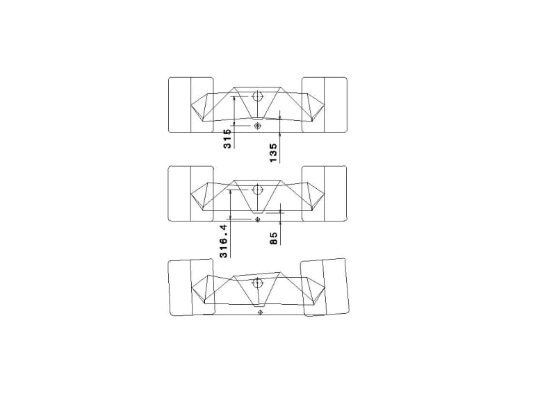
I was wondering how roll center migration affects suspension performance during roll movement.

I have carried static suspension calculation, and I did not see any releveance of non migration roll center suspension, but my calculation are static not dynamic.

Do someone had experience on no roll center migration suspension and how it performs?

Regards

 
Replies continue below

Recommended for you

Millions of cars have been built with MacPherson front suspension which inherently has enormous instant center migration. They work well enough for most people.

The only type of independent suspension that does not have migration relative to the bodyshell are the swing-axle-type (including Ford Twin-I-Beam) or single trailing or semitrailing arm type, that have a single defined pivot axis fixed to the bodyshell. They all have bad side effects. The "cure" (to the imaginary/nonexistent "problem") is worse than the "disease" (that the instant centers are not fixed in space relative to the bodyshell).

The only types of suspension that do not have migration relative to ground level are certain rigid-beam-axle types, depending on the design of the mechanism that locates the axle side-to-side.

What imaginary problem are you trying to solve by not having instant centers that move around?
 
Mac pherson is a cheap solution for production car, wich you are right work well for most people.

I was dealing about upper and lower link wich are use on race car.

On this configuration, if the link are not too short, it is possible to design a suspension with no roll center migration (without computer).

Most of book carry calculation with roll center, as this point is often moving, this could be a problem, and calculation went wrong or need further itterations.

Some author mention a good suspension is when the distance of roll center to the center of gravity, do not vary.

I was only asking if some people on this forum have already test or experience suspension with upper and lower link with no roll center migration relative to center of gravity?
 
The instant-center of an upper and lower A-arm suspension will most certainly move relative to the bodyshell or center of gravity, especially in two-wheel bump. If it's in bump (or if someone has lowered the suspension!) the upper and lower arms will both be pointing and intersecting at a different spot than they will at nominal ride height. The ONLY way the instant center stays in the same exact spot relative to the center of gravity is if the suspension physically has its single pivot axis there. That's Ford Twin-I-Beam, or pure trailing or semitrailing arms (or its extreme variant, swing-axle). An upper and lower A-arm design cannot do this ... unless the A-arms physically are extended across the car to meet in the same physical point ... which is swing-axle geometry (or Twin-I-Beam which is the same concept).

In dynamic situations you really need to be using force-based analysis, not necessarily focusing on the "roll center" which (for most independent suspension designs) is an imaginary construct anyhow. What's happening at the outside wheel matters far more than what's happening at the inside wheel because there's much more force on the outside wheel.

Upper and lower A-arm suspensions allow much more design flexibility in terms of camber gain, anti-squat, etc and they remove some practical geometry limitations imposed by MacPherson, but the instant center motion is a small part of this.

It will help to know what sort of vehicle you are talking about here. For example, Formula 1 cars don't have much camber gain with suspension movement and the instant centers are probably close to ground level far on the opposite side of the vehicle ... but it doesn't matter, because the suspension is so stiff that it hardly moves, and it doesn't have to move much because they're designed for use on smooth tarmac, so they have extremely high spring and damping rates. If you are talking about a World Rally car, or perhaps a desert-racing truck that is expected to go over uneven terrain at high speed ... you have a much greater challenge at hand, because now it has to function over a wide range of movement.
 
Brian,

I prefer to join you a picture of the suspension I mention (sport car , formula ford, etc). It is 2d example, not 3d, but a good start.

Formula 1 is not interesting, because wishbone are placed for aero reason (mainly at the front).

You mention instant center movement, but I never mention IC movement, I understand your thinking: for no roll center movement you need no IC movement.

I only mention distance from roll center to COG keep the same.

If you have an example of suspension to submit me, and if you leave me one point free, I will be happy to show you that it is possible to limt near minimum , roll center movement regarding COG.

To minimize roll center migration relative to COG, it is the same construction problem as having no bumsteer or no cvd plunge, it is a 3 link compatibility problem.

To my knowledge, Instant center is an important point, this position deals with track variation and camber gain, the tangent of this point deals also with camber gain (length ratio between lower and upper links).

 
Draft_1_up9ys3.jpg
 
I don't have a method of creating an illustration and posting it here.

Now ... Take that diagram and draw in the instant-centers. I'm going to guess that the instant-center of each side (where the projections of the control arms intersect) is about 1 vehicle-width on the opposite side and close to ground level.

Then ... Lower the bodyshell by (let's say) 50mm and re-draw your instant-centers. They'll be below ground level.

Then ... Go back to nominal ride height and re-draw with 5 degrees of body roll. It's quite possible that the instant-center of the outer wheel could end up pretty close to ground level. I don't know where the inner one will end up but given that the arms will be going closer to parallel, it's likely to be far off to the opposite side of the car. But we don't care much, because most of the weight is on the outer wheel, not the inner one.

So, you have fairly low vertical motion of the instant-center of the outer wheel (the one that matters) in roll (and we don't much care what the inner one does), but you have considerable motion in two-wheel bump (it goes below ground level).

The reason I refuse to extend the discussion to the "roll center" is that it's an artificial construct because the concept doesn't account for most of the forces involve the outer wheel rather than the inner one.

Now ... Explain to the rest of us what it is that you are actually trying to accomplish. "The big picture".

Circuit-racing cars have instant-centers close to ground level at nominal ride height (not necessarily at other ride heights - but these cars always carry the same well-defined payload) and with minimal vertical motion in roll. "So what".

This type of car normally has really stiff springing and dampers. The suspension hardly moves, anyhow. If you hardly let it move, it hardly matters what the instant-centers do. Circuit-racing cars of this type use that suspension layout because it works with the packaging and it works with the aerodynamics, and the geometry is good enough. (MacPherson would not be a good choice!)

It gets MUCH more complicated when you go desert-racing and you actually need large suspension movement. It also gets MUCH more complicated when you try to develop a road car that is expected to have good steering characteristics and good grip and good ride quality and do so whether the driver is alone on board or is carrying 3 passengers. And then you end up with MacPherson front and twist-beam rear anyhow because the bean counters dictated thus ...
 
Brian,

My initial post was regarding if anyone has tried a suspension with no Rc-COG variation, and what was the result?

You post, by trying to explain me that on Upper and lower A-arm suspensions, achieve no Rc-COG variation is not possible because Ic move.

I reply: it is possible to minimize RC-COG, and ask you to submit an example, so I can show it is possible, you reply : I don't have a method of creating an illustration and posting it here.

So what I say is: I have a method to construct a twin arm suspension wich minimize RC-COG distance, I posted below an example:
upper figure are +-50mm travel
middle figure is static
lower figure is 5° roll
rc_constant_2_o7q1wi.jpg

same wich Ic drawn
rc_constant_2_IC_mffmdx.jpg

Ic is moving but RC-COG alter of 3mm

The big picture is: I create a program calculate every force on suspension element under lateral and vertical acceleration, wich give me a good idea of what happen in a steady state corner (roll).
I find a construction to design parallel twin suspension with small RC-COG distance variation. I did not see any interest of this with my program, but I have the feeling that it could be a plus in dynamic, so I ask if somebody had always tried a twin arm suspension with small RC-COG variation, and if yes what was the result?
 
Your first diagram isn't what I meant. You drew the left side 50mm into bump and the right side 50mm into rebound. What I meant was the situation where BOTH sides are 50mm into bump, or BOTH sides are 50mm into rebound. You should find that the former situation places the roll center below ground level, and the latter situation places the roll center above ground level.

Lots of race cars - practically all open-wheel race cars - have been designed with suspension generally like what you are illustrating, which has relatively low instant-center height movement in roll. For that matter, lots of street-driven cars are like that, too. And it's been done since the 1950s if not before.
 
Brian,

I m not dealing with Rc relative to the ground, I m dealing with RC to center of gravity COG distance, which is generally use to calculate roll moment in litterature.

'Lots of race cars - practically all open-wheel race cars - have been designed with suspension generally like what you are illustrating, which has relatively low instant-center height movement in roll. For that matter, lots of street-driven cars are like that, too. And it's been done since the 1950s if not before.'
I do not know what you want to explain, and I do not understand the sense, if you want to say that kind of suspension is well know, it is evidence.
what is more evident is to keep RC-COG variation small is less evident and most author mention the importance of limiting Rc movement regarding COG.

Buggar,

'A raising "roll center" results in progressive roll stiffness. Laterally it does not matter'.

Do you have experience or calculate this affirmation?
 
Draw the diagram that I suggested. You've drawn it at nominal ride height. Draw it again with the body 50mm below nominal ride height, and draw it again with the body 50mm above nominal ride height. With that suspension design, the roll center moves relative to the center of gravity ... it is not a fixed distance from the center of gravity. DRAW THE DIAGRAM.

If you don't know what I'm explaining ... I don't know what you are asking. I have a feeling that English is not your first language, and something is getting lost in translation.

"Do someone had experience on no roll center migration suspension and how it performs?" Well firstly, the roll center DOES move, so claiming that it does not move is not completely correct. It may move less than with other designs, but it does move, so that's part of the response to this question from your first post. If your question then means "Does someone have experience with suspension designs that have relatively low motion of the roll center relative to the center of gravity", given that this general suspension design has been in use for 70 years if not more, the answer would be "yes". And at this point, I don't know what you are asking.
 
Case in point was when we went from watts link beam axle to IRS. RCH vertical migration is roughly 0mm/mm jounce for the Watts, and say 0.5 mm/mm for the IRS. I've never found any physical meaning for lateral migration.

On a smoothish track or public road there was no difference in everyday handling. Sure on rough roads it was easy to pick (our proving ground's main access was a 5 mile gravel road).

Cheers

Greg Locock


New here? Try reading these, they might help FAQ731-376
 
Brian,

I DRAW the diagram as you asked
ride height -50 from static
rc_constant_2_-50_knkgnp.jpg

ride height +50 from static
rc_constant_2_50_rswg0g.jpg

So Rc to COG distance alters by 1.4mm.

I did not DRAW the IC line, I can do but it will make small picture difficult to read.
I can sent you the file (dxf, dwg) and you be able to control by yourself that I did not cheat, and I know how to DRAW a roll center.

On my previous post, I draw one side +50 and the other -50, as far as it is symetrical, I put on one wiew 2 cases, may be it was not clearly understandable for you.

English is not my native tongue.
 
Greg

'ase in point was when we went from watts link beam axle to IRS. RCH vertical migration is roughly 0mm/mm jounce for the Watts, and say 0.5 mm/mm for the IRS. I've never found any physical meaning for lateral migration.'

You means rc migration relative to the ground, but relative to COG it is not constant in compression, rebound.
 
Lateral geometric roll center location doesn't enter into the SAE's definition of suspension roll center.

Nor does lateral RC location enter into lateral load transfer summations done up as LLT through the roll centers + LLT through roll and suspension roll stiffnesses + LLT due to unsprung mass effects.

I think Brian is hinting at taking a lateral-anti approach, where the inboard and outboard force effects are neither equal nor symmetrical.


Norm
 
Yup, I just gave up trying to explain. In a real car with actual suspension travel and a non-zero center of gravity height, neither the geometry (due to suspension movement in roll) nor the force distribution (due to C of G height combined with front/rear load distribution due to all of the roll stiffness components) are symmetrical left to right, so what is the relevance of an imaginary geometrical intersection of two lines on a drawing?

The instant-center of each side can be a useful concept, because if you know or can estimate the left-to-right load distribution, you can work out the vertical components of the forces on each side separately - at least for steady-state cornering.

It will turn out that it more-or-less matters for the outside wheel, and it more-or-less doesn't matter for the inside wheel.

Hence why the millions of cars built with MacPherson front geometry work well enough even though the instant center in droop (inside wheel) does all sorts of screwy things. The weight isn't on that wheel, so it doesn't matter.

"Roll center too high at nominal ride height or in bump = BAD". That's about all that really matters.
 
Status
Not open for further replies.
Back
Top