Continue to Site

Eng-Tips is the largest engineering community on the Internet

Intelligent Work Forums for Engineering Professionals

  • Congratulations KootK on being selected by the Eng-Tips community for having the most helpful posts in the forums last week. Way to Go!

Roll center migration 1

Status
Not open for further replies.

Bluefoxy

Automotive
Apr 9, 2020
38
Hello,

I was wondering how roll center migration affects suspension performance during roll movement.

I have carried static suspension calculation, and I did not see any releveance of non migration roll center suspension, but my calculation are static not dynamic.

Do someone had experience on no roll center migration suspension and how it performs?

Regards

 
Replies continue below

Recommended for you


Brian,

You wrote: 'Well firstly, the roll center DOES move, so claiming that it does not move is not completely correct.', I spent some time to design with your request (+-50 mm, etc).
Do the image I posted convince you that is possible to limit this movement at the minimum?

I undertsand your meaning regarding with production cars wich mass are not centralize, so drawing a central point has no meaning, but on most race car, weight is central, or at least it can be set up with corner weight.

MacPherson work well enough on production cars, but mainly the use of MacPherson is relative to cost ,and the possibility to leave space for the engine, but it generates friction and camber gain are small. I never see a proper race car (signle seater or sport prototype) design with MacPherson.

For a twin arm suspension, regarding IC, vertical distance IC to the ground define the amount of track variation, you will get. Lateral position of IC define the camber gain, but if you draw the IC tangent (wich belong to upper and lower link ratio) it define also the camber gain linearity.

When you mention the useful concept of IC, do you refer to WC Mitchell FAP document?

Regards
 
Certainly you can minimise the roll center movement. You've shown that you have done so. My point is, "So what". It doesn't matter, as long as the instant center of the outside wheel when loaded up while rounding a corner isn't too high, and as long as it isn't too high when rolling down the road. Beyond that ... It doesn't matter.

I'm not talking about static location of the center of gravity. I'm talking about the instantaneous forces on the wheels while the car is rounding a corner.
How relevant is the position of the instant-center of the left front suspension of this car at this particular moment in time?
In terms of the instant-center heights ... the only thing that matters, at that particular moment in time, is the geometry of the right front suspension. The left front suspension is - literally - just along for the ride. (and by the way, that car uses MacPherson front suspension!)
 
Bluefoxy,
Yes I have my "Chassis Roll Study" in different files all over my computer. I have some in pdf file format which this forum doesn't eat. I have posted some of my studies on this forum but have no idea where.
 
Just a bit more going on besides load transfer in cases where the 'roll center(s)' i.e. 'roll axis' shifts around during cornering. The sprung mass exhibits most of this motion which you can easily see (for example) if you watch our 'rail shipping simulator'. Each end of the vehicle moves laterally in accordance with the ground plane side forces.

So, roll axis displacement laterally not only shifts the weight transfer trajectory, but it moves the nose and/or tail of the vehicle, often producing sensation of yaw angle or sideslip motion that may or may not be a real good cue to the driver.

Make up a soda straw model of the unsprung and sprung masses with the 'roll center' points connected to the unsprung axles via springs from a couple of writing pens. A hot glue gun is a handy way to put this together. Then push on the sprung C.G. and watch for yourself as the sprung mass orbits. This is why the front and rear motions need to be 'coordinated.

Makes for a great video, especially when Safety Lab targets are placed on the bumpers and photogrammetry analysis is done.
 
By logic, the height of the "roll center" is a measure of chassis roll stiffness when subject to lateral force. If the "roll center" is rising, the chassis roll resistance is tightening up.
(I dislike the term "roll center", but I realize what is meant).
 
Here's the hardware for this experiment. They usually put signals into it from actual rail car rides across the country. There are certain spots on some routes where enormous accelerations are recorded. (including sustained 9g steady state cornering forces. [Bet you can't figure out how this happens: Too many propeller heads playing with their 'unrepresentative' model trains at work].
 
 https://files.engineering.com/getfile.aspx?folder=abe2d22c-df31-45a5-934c-9fbe166da674&file=rail_shipper_Simulator.JPG
There is a paper around where somebody calculated the geometric roll center height, and the force based roll centre height, as a vehicle went around the corner. They moved in different directions. GRCH is basically an instantaneous centre of rotation construct, it doesn't seem to me that that automatically translates into something drivers would care about.


Cheers

Greg Locock


New here? Try reading these, they might help FAQ731-376
 
Brian,

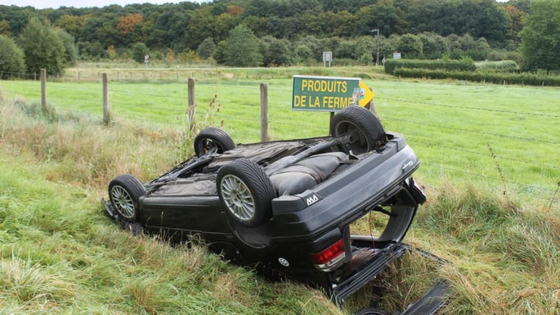
On this particular case, I will be pleased if you could tell me more about the instantaneous forces on the wheels :
case_r9eg82.jpg
 
cibachrome

'So, roll axis displacement laterally not only shifts the weight transfer trajectory, but it moves the nose and/or tail of the vehicle, often producing sensation of yaw angle or sideslip motion that may or may not be a real good cue to the driver.'

It sounds logical.
 
Bluefoxy said:
Brian,
On this particular case, I will be pleased if you could tell me more about the instantaneous forces on the wheels :
I will have a guess and say at some point prior to the photo, a large roll moment was generated.

je suis charlie
 
The rear suspension is the notorious twist axle with the cross beam centroid and shear center facing downward and foreward a bit. That means it has -10% --> -12% rear roll steer (as in roll oversteer). It takes a mighty stiff tire to compensate for this at speed below 140kph. With those stiff tires, the roll and yawrate frequencies hooked up and the driver ran out of courage.

The camber of the front and rear wheels is permanently deformed due to the wheels sinking into the ground and the vehicle was tripped while going sideways. Look at the tracks. Loss of control due to the very high gain of the car, low understeer [less than 1.25 deg/g] and rain tread for wet traction. Axle loads > 5g (typical design max).

Then driver screwup! Just push it over and drive it away. Might want to clean the seats first...
 
The fact that macP front twistbeam rear can be made to work successfully is probably proof that in the vehicle dynamics world we spend a lot of time worrying over stuff that doesn't matter, or perhaps that we are such geniusses that we can make even bad solutions work. I wonder which it is.


Cheers

Greg Locock


New here? Try reading these, they might help FAQ731-376
 
Greg,

MacPherson work well enough on production cars, but mainly the use of MacPherson is relative to cost ,and the possibility to leave space for the engine, but it generates friction and camber gain are small. I never see a proper race car (signle seater or sport prototype) design with MacPherson.

I created this thread regarding race car suspension, upper and lower arm, not MC Pherson. And ask if someone had ever try this kind of suspension with a roll center to distance remain constant and if they see any interest?

Brian mention: it does not matter because of assymetrical and so on, and it was not possible to have RC to COG distance remains constant. I spent time DRAW, to show him it was possible.

You mention watts link, clearly it does not keep RC to COG distance constant.
You mention Force based roll center, I reply by joining the Mitchell document which deals with Force based roll center. I do know not if you read it

If your reasoning is: On Mac Pherson, roll center migration is massive , and Mc Pherson work pretty well for production car, so thinking about migration roll center is irrelevant. It is taking 2 facts without any link, to conclude something wich allow you to not ask you question.


Bluefoxy said:
I created this thread regarding race car suspension, upper and lower arm, not MC Pherson. And ask if someone had ever try this kind of suspension with a roll center to distance remain constant and if they see any interest?

More or less, every open wheel race car since the 1950s.

Who do you expect to be "interested"? (Do you think people who have been working with vehicle dynamics their whole career don't already know how to do what you are suggesting?)
 
No interest because no one in their right mind uses kinematic roll center technology. Its an artifact of desk calculators and drawing board technology. Asymmetric suspensions rule out the use of this analysis. Mother Nature does not use kinematics for anything. [Just like she doesn't do a matrix inversion everytime she integrates accelerations to get movement]. "Yes or No ?" Take Claude's course, it's covered starting on page 666 in the spiral notebook.
 
Brian,

'More or less, every open wheel race car since the 1950s.' It is your opinion,I do not think it is clever but I respect.

For sure and in any case it will interested people who had spent their whole carrier working on vehicule dynamics, and end up thinking: Mac Pherson works pretty well.

Cibachrome

'No interest because no one in their right mind uses kinematic roll center technology', that mean Eric Broadley, John Barnard, Robin Herd, Caroll Smith, Allan Staniforth loose their time with roll center?

Do one of you have work in race car design office?

 
Yep. What's your point? Race car engineering is relatively easy. Production Vehicle Dynamics is much harder. Comfort, cost, rules and requirements, foreseeable misuse, aftermarket parts, drivers and operators with limited skills and abilities, high mileage durability, maintenance, wearout, production volume, global specifications, multiple suppliers of the 'same' part, safety, packaging, customer xpectation, fuel economy. The list can go on.

Once you've had a few 'racecar' prototypes (spelled both forwards an backwards) on K&C machines, simulators and tire test machinery, you realize that all they are is super tires, super motors, super drivers, super expensive, titanium, kevlar and not a great long term career move for engineering staff. But pretty simple to analyze. Small angle approximation works for everything except crankshaft rotation.

BTW: show us a graph of your comparison of kinematic roll center vs. FB 'roll center'. Jus a leetle beet of kombliance make all bets off. Yes or No ?
 
Race car engineering is relatively easy: In the sixties, it took million USD and 3 years to Ford to beat Ferrari at Lemans. Look how many manufacturer involve time and money to never win a F1 race or Lemans.
This affirmation have no sense.

In my carrer, I have been working as engineer for production manufacturer and race car manufacturer. Production and race car design are both not easy.

BTW: show us a graph of your comparison of kinematic roll center vs. FB 'roll center': FB you mean Force Base according definition of Mitchell?

'Jus a leetle beet of kombliance make all bets off.', sorry but english is not my native tongue, I tried google traduction but did not get the sense of it.
 
Status
Not open for further replies.

Part and Inventory Search

Sponsor