Continue to Site

Eng-Tips is the largest engineering community on the Internet

Intelligent Work Forums for Engineering Professionals

  • Congratulations KootK on being selected by the Eng-Tips community for having the most helpful posts in the forums last week. Way to Go!

Salesforce Transit Center closes due to cracked support beam 16

Status
Not open for further replies.
Replies continue below

Recommended for you

That's a beautiful structure.

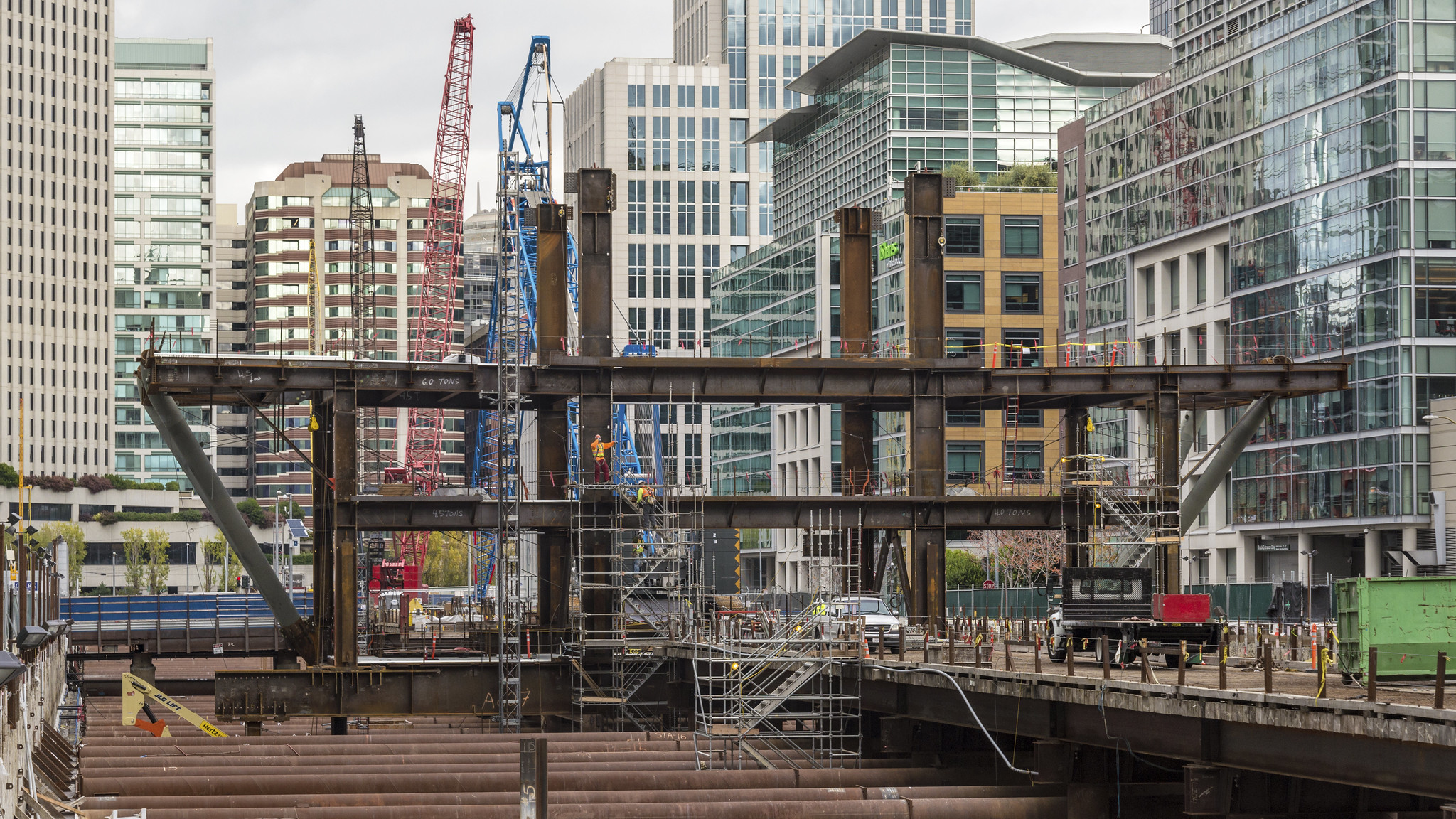
That center section is highly indeterminate (and highly fixed) so the potential stresses due to temperature, displacement, or misalignment effects could be massive.

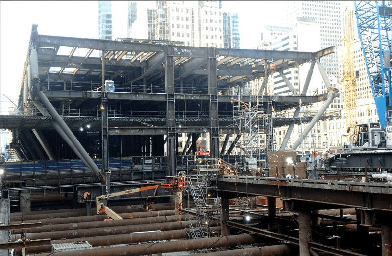
transbay1.jpg


15910307851_b30f0f6f35_k.jpg
 
Another engineer in our office who looked at it proposed that the cracks may be due to too much or too little preheat for the welds, considering the flanges are 5" thick. It's supposedly very tricky getting preheat right for something that thick.
 
I was going to ask about "weld metal" (manufacturer of the rods, rod disciple, inspection results and welder performance), but this particular crack is near the welds, but not across them.

Preheat/no PWHT stress problems are likely.
 
Has the steel grade been mentioned? I would agree with HotRod10 on the possible critical control of the preheat. Sure would like to see the welding procedures and the mill certs as well as the welders qualifications. Probably special inspection and tests were required. There's some good welding consultants and metallurgists in the SF area who have a lot of experience with the Bay Bridge issues.
 
Emily Pollock said:
...is not yet sure why the support beams collapsed...
Um, the beams only cracked, they didn't collapse, right?
 
I'm still not clear on where these beams are supported and how they span. They are deeper in the middle, which would indicate they are supported at the ends, but there is supposedly a "column" at the middle, which I would have assumed was actually a tension strut (an assumption bolstered by the statement in another story saying the beams "support" the weight of the bus deck below). However, the graphic depiction from the SF Chronicle shows an arrow under the "column" pointing upwards, indicating it is actually a support column.
 
RoopinderTara

Article seems to be in line with other information I have read about the situation. The graphics is a very nice touch.

A coupe of comments (not really about the article).

I used to work in offshore and we did a lot of very deep very heavy plate girders. I was onsite at the fabricator and used to watch them (not as inspector) weld up the plate girders. There is a lot that goes into this type of fabrication so I would question if the engineer/detailer/fabricator had experience in similar heavy plate design and fabrication.

Personally I find professionals who speculate on causes in situations like this in a forum read by the public without access to all the design information (drawing, details, etc.) to be doing a bit of a disservice. I don't think any of the statements are false but they could imply gross amount negligence on the part of the design engineer. I don't know the full text of what was said but as reported the statement about too much weight on the beam implies a design error in the loads which is a pretty serious accusation. Maybe to laypeople that doesn't jump out but to me when I am involved in a forensic investigation I am very careful not to even imply a design or fabrication error unless it can be conclusively proven. Commenting on observable facts and translating the situation into laymen's terms would be a more appropriate course in my opinion.

Regarding the beam/column - I would call that column a hanger since it appears to be holding up the deck below (and in tension). That is just my opinion - maybe AISC has some standard glossary of terms?

Hopefully when a full report is issued we'll be able to read it and learn from whatever mistake(s) were made.
 
It looks like the cracks are in the bottom flange but I can't really tell for sure from the limited information. Assuming that's correct, could not this be caused at least in part due to an overloading of the beam in the middle, which could be caused in part by settling of the supporting column?. I realize the forces are very complex but if the beams have failed on the tension member, and the structure seems to have moved somewhat in order to produce a gap, I wonder, as this is right next to the Millenium Tower.

Brad Waybright

It's all okay as long as it's okay.
 
Now that I see where the cracks are located, in addition to the aforementioned potential issue with weld preheating, another possible contributing factor could be moment on the hangers due to unanticipated movement of the bus deck below.

Of course, the restraint effects of using a web as thick as the flanges, which is not typical for large I beams, is also a big question in my mind.
 
@RoopinderTara -- "Apparently, the mistake is still under investigation" seems like odd phrasing. Did the author mean "The apparent mistake is still under investigation"? As written, it implies that the status of the investigation is unknown, which seems unlikely.

TTFN (ta ta for now)
I can do absolutely anything. I'm an expert! faq731-376 forum1529 Entire Forum list
 
OK - so that beam was temporarily supported. Not knowing the entire configuration of the structure my mind immediately asked - what other beam-cracks may have occurred and where?


Check out Eng-Tips Forum's Policies here:
faq731-376
 
There are two such bridge spans, the one with the crack spanning Fremont St. and another to the west at First St. The TJPA will be shoring both, though the Fremont St. location is the only one that has cracked. News Video: Link

The yellow jacks are 100 ton capacity and the blue jacks are 800 ton capacity.

Original Press Release with As-Built photo (PDF). Link

ENR photo of steel erection: Link

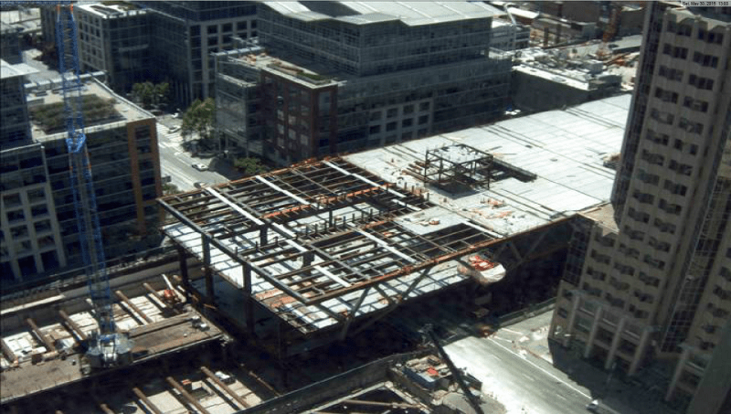
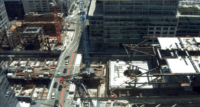
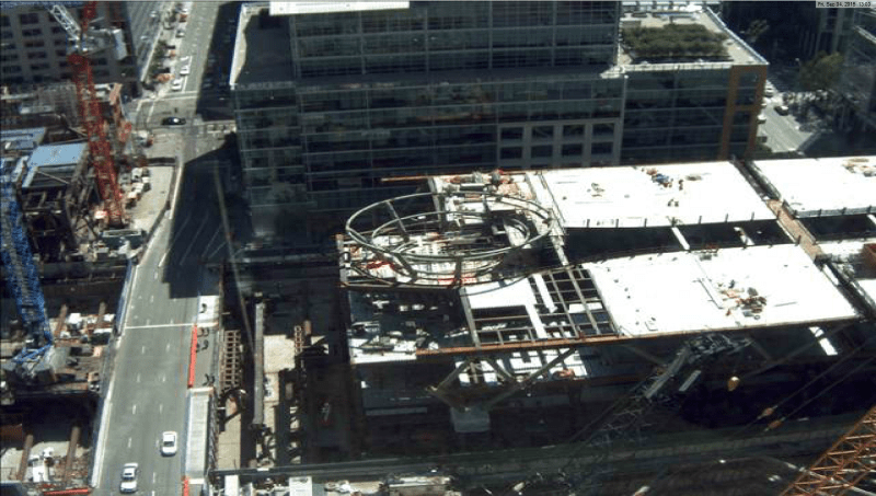
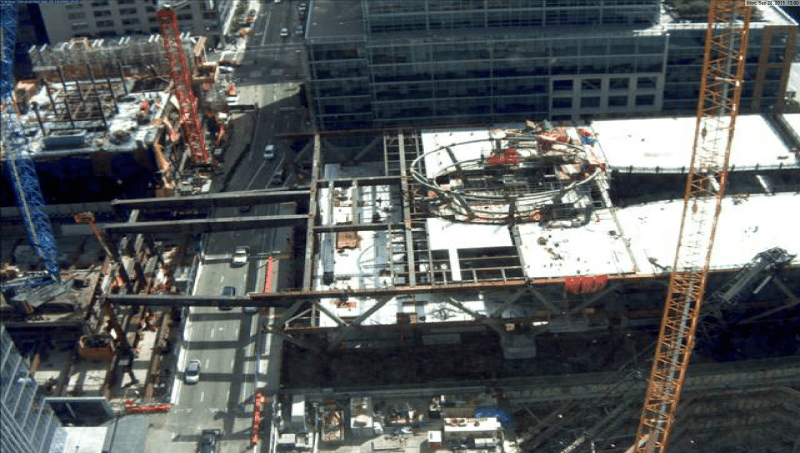
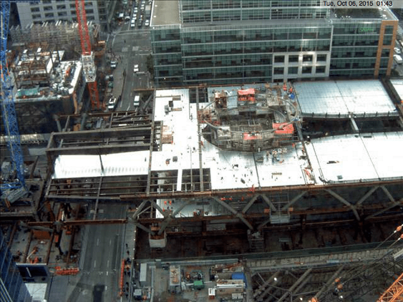
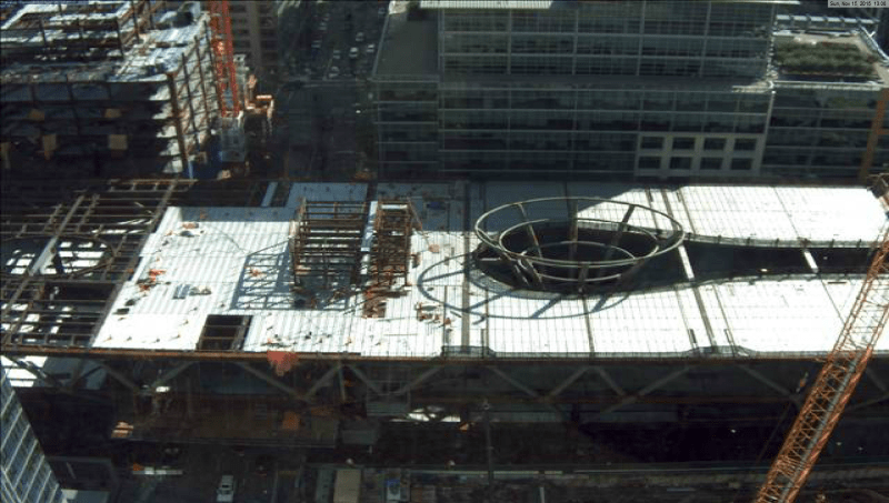
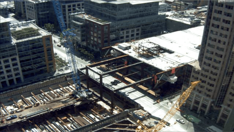
WebCam grabs:

First St.
TJPA-First1_hajitc.png

TJPA-First2_lzvsso.png


Fremont St.
TJPA-Fremont1_juadd6.png

TJPA-Fremont2_ufyqoa.png

TJPA-Fremont3_otzza7.png

TJPA-Fremont4-1_mvua1h.png

TJPA-Fremont5_koumvv.png

Looking north with Millennium Tower on the right.
TJPA-Fremont7_b0lyip.jpg

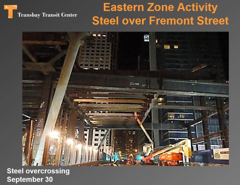
Steel having just spanned Fremont St.
TJPA-Fremont8_cqjuok.png
 
I'm curious how that raft is constructed and what the target bearing pressure is for the street.
 
epoxybot said:
The yellow jacks are 100 ton capacity

Really, only 100 ton capacity...from a hydraulic/ram area perspective they look like closer to 1,000 ton capacity. Given their effective length I can see reductions in the load capacity, but only 100 ton. I have several 100 ton hydraulic hollow rams and they are 8" diameter - sure, they are only 8" tall.

 
ENR said:
Skanska USA Civil West held the $189.1-million subcontract to furnish the building’s 23,000 tons of structural steel and erect the entire system, including the building’s exotic exoskeleton

So in the SF Bay Area erected structural steel work goes for about $8,000 per ton - I know this was a one-off type project, and used Buy America steel, but wow!
 
And I only got $0.06 per pound ($120/ton) for steel scrap earlier today.
 
Compositepro said:
And I only got $0.06 per pound ($120/ton) for steel scrap earlier today.

Lucky you. In my area we have to pay the recyclers to dispose of steel scrap. Really, we do.
 
Status
Not open for further replies.

Part and Inventory Search

Sponsor