Continue to Site

Eng-Tips is the largest engineering community on the Internet

Intelligent Work Forums for Engineering Professionals

  • Congratulations KootK on being selected by the Eng-Tips community for having the most helpful posts in the forums last week. Way to Go!

Second case, profile callout

Status
Not open for further replies.

Andera

Mechanical
Jan 21, 2019
58
I got the following explanation seen below, but I would like to ask if you agree with the assessment? I see here are many GD&T experts that can help me with my follow up questions.
Unfortunately, the discussion I had, has been deleted on the original site, as the people there (original creators) I assume were not happy with the additional questions I’ve been asking them.


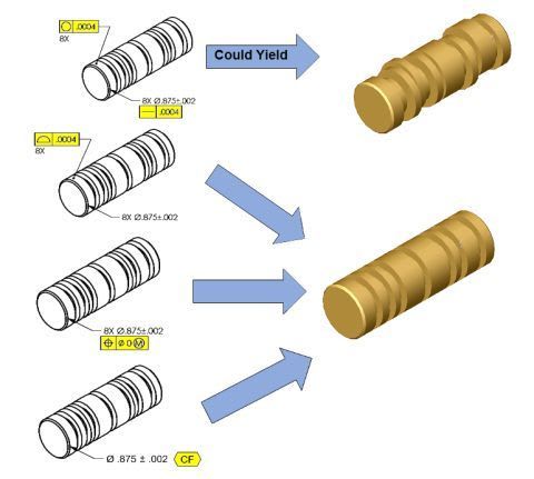
The second example is a refinement of Rule #1. As such, it would be inappropriate to have a basic dimension on the size.
If you are not familiar with the hierarchy of GD&T, Profile of a Surface, with a datum reference, can locate &/or orient a feature wrt the datums. Without a datum reference, if the feature is an enclosed boundary, then it will control size and orientation of the feature. If the size is already controlled, and a profile of a surface control is applied without a datum reference, it controls the form of the feature.
In the second example, what is being controlled is co-cylindricity of the 8 surfaces. The only geometric control that locates surfaces is .... profile of a surface.
If you're not familiar with the hierarchy, it's a good time to look at GD&T from that perspective.
I would like to see update the graphic to include a composite profile control as another option

TE_-_Copy_txepnf.jpg
 
Replies continue below

Recommended for you

Greenimi,
Here is another quote of Dean, from the thread in your first link:

17 Jul 11 16:31
"Profile on a cylinder absolutely requires a basic diameter."
 
Burunduk said:
And what would happen if the measurement is programmed without a CAD model? Would the profile requirement work at all without an input of basic diameter that normally results in a size (and form) control by the profile?

I don't think a CMM would handle profile without assuming the diameter is basic.
 
Greenimi,
Regarding Evan's statement where you quoted him to say: "The usual location-controlling aspect of profile is magically overridden by the presence of the directly toleranced dimension. It's horrible."

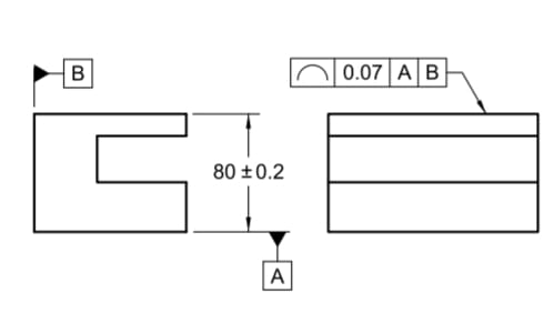
He refers to this figure:
Screenshot_20230324_081800_Drive_zlqnrp.jpg


The location control is not overridden by the presence of a directly toleranced dimension.
The location controlling aspect is overridden by the absence of a basic dimension. The true profile is not located relative to the datum reference frame. It is only oriented to it by an implied basic 0°.
Even if the drawing was referring to a model from which basic dimensions are queried, you can't have both. If a toleranced dimension is given, the same dimension is not interpreted as a basic dimension for query from the model. It would contradict the fundamental rule against providing more dimensions than necessary for a complete definition.
 
Long story short, the information about behavior/mechanics of the tolerance zone should be encoded into the feature control frame only.

But here is the thing with the 2nd drawing in the OP's post. Had the considered feature been a single cylinder, they would have simply used a cylindricty tolerance. But since these are multiple features, the only way that seemed workable for them to group the 8 individual cylindricity tolerance zones was to specify profile (since it is a tolerance that has grouping capabilities). In '94 the continuous feature concept did not exist yet. From '09 going forward, the CF concept can be leveraged, but I think it will still require specifying the <CF> modifier right next to the cylindricity FCF.
 
pmarc said:
the information about behavior/mechanics of the tolerance zone should be encoded into the feature control frame only.

I take "behavior/mechanics" to mean the definitions of whether the tolerance zone is fixed by certain dimensions, or it can contract/expand, or float relative to the datum reference frame to contain the as-produced feature.
And I completely agree.
If the feature control frame includes the profile of a surface symbol and the default for profile of a surface tolerance zone is to be static and fixed in one way or another to the true profile specified by basic dimensions, only a unique modifier in the feature control frame can override this default, for example by allowing the tolerance zone to contract/expand. That would be the dynamic profile modifier.
If a basic diameter is missing as in the 2nd example in the OP, the profile tolerance zone's definition is simply missing an input which should cause an "error" in its application - it just can't work.

pmarc said:
From '09 going forward, the CF concept can be leveraged, but I think it will still require specifying the <CF> modifier right next to the cylindricity FCF.
As you probably know, the CF symbol can be placed either near the size dimension and tolerance or near the cylindricity callout. Of course, it would operate differently in the two cases. In case it is adjacent to the size dimension and tolerance as in the bottom case in the OP, the meaningful implication is that the entire interrupted feature is evaluated for perfect form at MMC in a single boundary.
If applied to cylindricity, the cylindricity tolerance zone becomes common to all portions of the interrupted feature.
Although differently and to different levels, both would control alignment.
 
Hi All,

I'm tempted to write a detailed rssponse, but based on the old threads that greenimi referenced it looks like I've written extensively on this topic already ;^).

The unfortunate fact is that we still have to guess at how a profile tolerance would be affected by the presence of a directly toleranced diameter dimension. The standard says that profile tolerances define a tolerance zone relative to a true profile, and then mentions applying it as a refinement of a size tolerance created by toleranced dimensions. In the same paragraph!

As we have seen again in this thread, different opinions can be formed based on the information in Y14.5 (depending on which pieces of information one chooses to consider and which to ignore, and what additional things are inferred).

Evan Janeshewski

Axymetrix Quality Engineering Inc.
 
Evan, the true profile that the standard refers to in that statement is only for the form of the feature itself. There's no contradiction in having the form be basic dim (such as one or more radii), but then the relationship to the datums be toleranced. That's the idea given in Fig. 11-32 (snippet given above); the datums provide orientation control, but not location. The true profile is the flat surface's nominal form (an infinite radius, I guess you could say).

Somewhere in those other threads, though, I think we all agreed that if it's not a flat surface then the orientation-but-not-location idea gets into a gray area that may be problematic. But I'd say that the statement in the standard by itself is non-contradictory.

John-Paul Belanger
Certified Sr. GD&T Professional
Geometric Learning Systems
 
Belanger said:
There's no contradiction in having the form be basic dim (such as one or more radii), but then the relationship to the datums be toleranced.

I disagree that toleranced dimensions can control a relationship to the datums. It's possible only with a dedicated note like shown in the standard for castings, forgings and molded parts, and as I think was allowed in Y14.5 until '94.
 
Burunduk, what about the example already given of Fig. 11-32?
Doesn't that example of profile have toleranced dimensions back to the datum?

John-Paul Belanger
Certified Sr. GD&T Professional
Geometric Learning Systems
 
Belanger,
I consider 80±0.2 in figure 11-32 to be a simple size dimension. It has no direct relationship with the profile of a line tolerance or the datum established for it. It certainly doesn't affect the profile of a line tolerance zone in any way.
 
Burunduk said:
It certainly doesn't affect the profile of a line tolerance zone in any way.
If that were the case, then the same callout without referencing datums A and B would mean the same thing as the current figure. But that isn't true.
Think of it this way...the profile tolerance must live within the size tolerance. Thus, profile doesn't control location, but it does control orientation, which is a refinement of location.
So I'll repeat my contention that profile can sometimes be applied to a true profile that itself isn't basically dimension to the given datums.

John-Paul Belanger
Certified Sr. GD&T Professional
Geometric Learning Systems
 
Belanger said:
If that were the case, then the same callout without referencing datums A and B would mean the same thing as the current figure. But that isn't true.
I don't follow.
Without referencing datum features A and B the profile of a line would only control form, like straightness would. As it is in the figure, orientation is controlled, but the size requirement of 80±0.2 has nothing to do with it.
If this directly toleranced dimension was removed from the drawing without being replaced by a basic distance dimension or dimensions linking to the datum, the orientation and form would be controlled by the profile of a line just the same.

Belanger said:
the profile tolerance must live within the size tolerance. Thus, profile doesn't control location, but it does control orientation, which is a refinement of location.
I agree that the profile of a line tolerance in the figure doesn't control location, and that it does control orientation (and form).
But what are exactly the implications of "profile must live within the size tolerance"? Does the part have to conform to both requirements to be accepted? Yes it does. But does the size tolerance or dimension take part in defining the tolerance zone for profile? I claim that it doesn't. The part could be, for example, 100 mm tall instead of the required 80±0.2, and still conforming to the profile of a line tolerance, within a very small measured value. It could be rejected only for non-conformance to the limits of size, imposed only by the toleranced size of 80±0.2. There is no reason to mix the two requirements. A good reason not to mix them is exactly because they use different types of dimensions - one uses a toleranced dimension, the other needs basic dimensions.
 
Perhaps we are saying similar ideas, but with different perspectives and wording. (I will amend my previous post.. the profile zone itself doesn't live entirely within the size limits, but the line elements must fall within both requirements, as you mentioned.)

My point is that the profile tolerance has some relationship to datums A and B; we certainly agree on that. So my comment (where you said you didn't follow) simply pointed out that dropping the datum references A and B would change the meaning of the profile tolerance.

Profile is not locked by the size tolerance. But my comment is that people often assume that any profile tolerance that references a datum MUST have a basic location back to that datum. Figure 11-32 is the prime example of why that's not the case.


John-Paul Belanger
Certified Sr. GD&T Professional
Geometric Learning Systems
 
Regarding the latest tangent to this thread, I think both of you are right in some way. In figure 11-32 the profile tolerance does reference the datums, but unlike most uses of profile, it's not a basic dimension for location (Belanger's point). The location is handled by the size tolerance.
Profile does control orientation, but there is still a basic dimension for orientation of 0 degrees (essentially that's Burunduk's and axym's point).

For the original question, I would agree that the second profile example is incorrect because it doesn't have a basic diameter.
 
Belanger,
I certainly agree that "that dropping the datum references A and B would change the meaning of the profile tolerance".

Belanger said:
But my comment is that people often assume that any profile tolerance that references a datum MUST have a basic location back to that datum. Figure 11-32 is the prime example of why that's not the case.
I will also clarify my point:
A profile tolerance can reference a datum without having a basic location to the datum, but if it does have a location back to the datum, that location must be basic.
This is why I initially said at 24 Mar 23 16:53 that "I disagree that toleranced dimensions can control a relationship to the datums".

In figure 11-32 the profile tolerance zone, or true profile, has no location relationship whatsoever to datum A, because it has no basic location relative to it.
There is only an implied basic 0° orientation. It is true that the feature which is controlled by profile is part of a feature of size, with the other part being the surface labeled as datum feature A. The size of that feature of size is controlled by 80±0.2. This is a size tolerance, and it does not use a datum feature and doesn't require the establishment of a datum. I guess it would not be wrong to say that this size requirement effectively results in an indirect limitation of distance between datum A which is used for profile of a line and the top surface, but that distance limitation is absolutely not part of what the profile of a line requirement imposes and not part of the definition of the 2-parallel-lines tolerance zones. The tolerance zones can float freely in translation relative to datum A, and have nothing to do with the toleranced dimension.
 
I am wondering what theory would Y14.5 offer if in fig. 11-32 the surface controlled with the profile of a line tolerance was nominally coplanar with datum feature A?
 
pmarc,
In that case, the shown nominal coplanarity would imply a basic zero location. Then the true profile would need to coincide with datum A, and profile of a line would control coplanarity by limiting the offset of the line elements from datum plane A.
 
Burunduk,
My question wasn't about what the interpretation of the line profile tolerance per the existing rules in Y14.5 would be in that scenario, but rather what solution they would propose to enforce the line profile tolerance zones to freely translate relative to datum A. Would it be a recommendation to apply a directly toleranced 0 dimension?
 
In that case, parallelism on a "EACH ELEMENT" basis for orientation (and form), and a profile of a surface for the control of coplanarity, would be the proper callouts.
 
OK, we are closing to the point I have actually already made by saying:
pmarc said:
Long story short, the information about behavior/mechanics of the tolerance zone should be encoded into the feature control frame only.

In other words, why didn't they just use parallelism on a "EACH LINE ELEMENT" basis in current fig. 11-32 instead of profile of a line?
 
Status
Not open for further replies.

Part and Inventory Search

Sponsor