Eng-Tips is the largest engineering community on the Internet

Intelligent Work Forums for Engineering Professionals

Simple Statics Problem? 3

Status
Not open for further replies.

Alexey881

Mechanical
Mar 24, 2013
18
0
0
CA
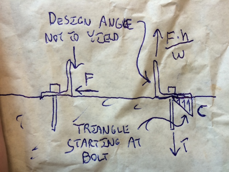
Hey everyone. How structural engineers would treat this problem if they had to determine all forces on all fasteners of a column loaded in the following way on top? (ignore weight)

h=w=10 in. a=b=1 in.

I've consulted several engineers, and each had a different way of resolving a force and of selecting a point of rotation, and in the end the answers of loads on the fasteners were very different. (some ways include prying, others don't) So what would you do?
 
 http://files.engineering.com/getfile.aspx?folder=29d8ac5d-a00c-4d85-8c94-19bf48a73c96&file=Prob1.jpg
Replies continue below

Recommended for you

If you have a particular geometry that is very common, people are going to spend a lot of time analyzing it and performing tests to verify or improve the analysis.

If you have some oddball geometry that you're not likely to see again, you have two choices. If it's a NASA project or something else very critical or expensive, you can spend a lot of time doing finite-element analysis and/or testing of models or full-size specimens. Or, if it's not worth that expense, you can come up with the best analysis you can, based on whatever approximations you feel are appropriate, and work it from there. In that case, the approximations made will vary greatly, as will the results, and that's what you're running into.

Note that it may be worthwhile using some more standard connection detail simply because a better analysis is available for it.

In summary, I'd probably work it the way one of those other people did.
 
For this example, if we can determine that the fasteners fail in a non-brittle fashion, and under good service, then any reasonable load path will suffice (the smallest tension will result from the largest moment arm - (13" - c/3). If the fasteners fail in a brittle fashion, or deflect too much, it makes sense to find another element that yields and redistributes the overstresses so that our simplified load path still yields a valid design.

For prying action on steel elements, we assume yielding of the base plate element (angle leg in this case) and verify that the steel will bend and deform before the stress on the fastener can be exceeded. If everything in the connection is brittle then the strategy is to detail the system to minimize load paths (add stiffeners to the angles and, to prevent prying, washers between the base material and the column) and increase the safety factor. This is appropriate when detailing steel for fatigue loads.
 
Ok for starters. Lets assume that the column is just a square block of infinite stiffness (so no deformation) and the force acting is 1000 lb. The angles are connected to concrete. keep in mind I need to design 3 things. (The fastener to concrete, the fastener to the column, and the angle thickness)
 
I don't disagree with any of the above comments but I think that this would be good enough for me. If prying is a big concern, there are two ways to reduce the uncertainty of that:

1) add a stiffener or two to the angles.

2) toss a washer on each bolt between the angle and the concrete (Teguci).

I doubt that either measure is truly necessary however.

For the design of the angle, I would replace the triangular stress distribution with a line load out at the toe.

image_fotec6.jpg


I like to debate structural engineering theory -- a lot. If I challenge you on something, know that I'm doing so because I respect your opinion enough to either change it or adopt it.
 
Find the moment created and figure out the tension required by the top angle. Assuming this is static loading and the load conditions will never change you can then design the bottom angle for the shear forces.
 
Hey KootK, without the fasteners (bolts) between the column and the angle it is easy to assume that the entire force F goes through the left angle as in your picture. However, when you have a bolt, or a weld , wouldn't you have the shear V being transferred to both, left and right angles? Then all your reactions would change. You would get a smaller T in your right anchor. So you would be designing for (possibly) smaller angles size.
 
OP said:
Hey KootK, without the fasteners (bolts) between the column and the angle it is easy to assume that the entire force F goes through the left angle as in your picture.

Easy? Pfft. There was nothing easy about it. It was the result engineering judgment honed over a couple of decades of professional practice my friend. I assumed that the shear would go 100% to the left angle because I see that as the stiffest load path, particularly as I suspect that the "box" will be thin a walled piece of equipment that would make the shear connection to the angle on the right hand side comparatively flexible.

That said, if you wish to be more conservative, simply design the bolts in the right hand angle for the tension that I showed and the full shear associated with force F. This should be of little consequence for the design of the bolt or the design of the angle. If you're close to the edge of your concrete, the shear force may need additional attention as it pertains to concrete breakout.

OP said:
You would get a smaller T in your right anchor.

I would never use the application of the force F in the right angle to reduce the bolt tension as I would deem that unreliable and unconservative. Remember, not all of your members will be designed based on the same force distribution here. A model that is conservative for one component may be unconservative for another. In the absence of knowing the "true" load distribution, we compensate by considering multiple distributions and applying them conservatively to the particular components under consideration.

I like to debate structural engineering theory -- a lot. If I challenge you on something, know that I'm doing so because I respect your opinion enough to either change it or adopt it.
 
Thanks a lot for the replies,
Right now i'm torn between three methods.

1) The one outlined in this forum

2) I've been told that we could take the whole column+angles attached as one system, then resolve the moment generated by force by dividing it by the distance between two concrete anchor holes. So in my case w+2a=12". And this approach neglects prying completely. However they'd use half the shear and entire tension on the concrete anchor on the right. (since shear is less detrimental to concrete this design would win with respect to anchors) (however im not sure how safe this is....)

3) I've been also proposed alternative solution where you divide the moment by the width of equipment and then use the resulted T as Tension on concrete anchor bolt. + add shear that would be half (F/2)=(1000/2)=500 lb (Because they want "to be more efficient"this load would result in smaller anchors then the one in method #1)

=(
 
In the proposed method, what is the justification for neglecting prying at the horizontal angle legs?

I like to debate structural engineering theory -- a lot. If I challenge you on something, know that I'm doing so because I respect your opinion enough to either change it or adopt it.
 
That if angles were (completely welded or completely rigedly attached to the stiff column frame, we could consider it part of the column and treat the entire system as one unit. And hence we'd be taking the distance between anchor holes now...
+ angle has to be super stiff
 
OP said:
That if angles were (completely welded or completely rigedly attached to the stiff column frame, we could consider it part of the column and treat the entire system as one unit. And hence we'd be taking the distance between anchor holes now...+ angle has to be super stiff

Rigid angles... rigidly attached... to a rigid body. It checks out so long as you're confident in the assumed rigidity of all these rigid things. If you're just holding down a sheet steel box, then color me skeptical.

TLHS said:
Looks like Koot's finally gotten to the point where he's literally answering questions on the back of a napkin.

The first draft was actually on the palm of my hand. I thought that looked desperate, however, so I borrowed a pen and some garbage.

Capture_jww68d.jpg


I like to debate structural engineering theory -- a lot. If I challenge you on something, know that I'm doing so because I respect your opinion enough to either change it or adopt it.
 
Thanks for a nice clear drawing :).

I think I'm going to do F*h/w to get pullout and apply it to fastener 1 (its a bit more conservative ...say to deal with some tiny prying)
The shear on fastener 1 will be F/2.

For fastener 2 I will apply Pullout=F/2 and Shear=F*h/w
(I will have some equipment inside that box, so the weight will counteract around 50% of overturning force. So (F*h-W*(w/2))/w will hardly ever be larger than F/2 for pull-out on fastener 2)

However, in both, yours and my methods: would you just toss in a random thick angle and say its thick enough?
And if not, then would you take fastener 1 forces and resolve them into T,V,M about the fastener 2 and then check the angle thickness and area against failure modes such as bearing, shear block, maybe buckling too?, etc.? Cause the way we assigned our forces, we'd never get a balance of Moments on the angle, hence cant really draw a moment diagram, hence cant really decide where to choose the location which needs to be checked for combined Tension, Shear, Moment)
 
That shear and pullout sounds fine, I'm assuming the tube and angles are made of steel or aluminum. If I were to fully perform a connection capacity check for everything at my office, I would just do a quick check of minor axis bending and bearing for the angles and wall of the tube, tear out on the wall of the tube and flange of the angles, and all of those fun failure methods in the connection chapter of the AISC steel manual related to bolted connections.

Unless these materials are made of something other than steel/aluminum or if your force is something large, I would go with the minimum thickness for an angle/tube and check that for adequacy, more often than not it'll probably be fine. The things I could foresee causing a problem before anything else is bolt hole bearing / rupture / bolt shear for the two angles anchoring the angles to the wall, so that especially should be considered. (Basically, everything that has anything to do with the fasteners)


Status
Not open for further replies.
Back
Top