Continue to Site

Eng-Tips is the largest engineering community on the Internet

Intelligent Work Forums for Engineering Professionals

  • Congratulations pierreick on being selected by the Eng-Tips community for having the most helpful posts in the forums last week. Way to Go!

Solid elements vs Continuum shell elements for modelling a core in a sandwich structure

spyros_ar

Student
Jun 1, 2021
10
Dear all,

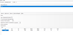
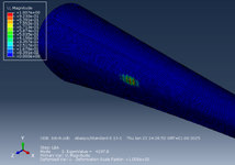
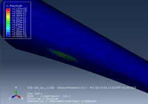
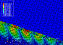
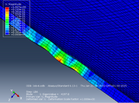
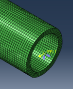
I am performing a linear buckling analysis of a sandwich structure, specifically a tapered cylindrical shell with reinforced patches. The face sheets are modeled using conventional S4R shell elements and are tied to the core vie TIE constraints. For the core, I used two different approaches:
  1. Solid C3D8I elements (4 elements across the thickness).
  2. Continuum shell elements.
However, I observed that the linear buckling analysis produces significantly different results between the two cases. For instance, in case (2), the critical buckling load is three times lower than in case (1), and the buckling position is also different for the same applied load. What could be the reasons for these discrepancies?
 
Replies continue below

Recommended for you

can you show the buckling mode shapes?
the continuum shells are only for the core?
what core properties are used with each element type?
 
can you show the buckling mode shapes?
the continuum shells are only for the core?
what core properties are used with each element type?
Yes the continuum shells are only for the core and again are tied to the face sheets (S4R). For both cases, the core is anisotropicand I assign material orientation via "Material Orientation Modulus"
 

Attachments

  • Core_Material.PNG
    Core_Material.PNG
    91.1 KB · Views: 3
  • Solid_Core.PNG
    Solid_Core.PNG
    380.3 KB · Views: 4
  • Continuum_Core.PNG
    Continuum_Core.PNG
    492.7 KB · Views: 3
Looks like it is a core shear crimping buckle mode. Which is why it is core element sensitive. Make a cut thru the thickness thru the buckle pattern area lengthwise, and show the mode shapes (zoom in on the buckle area).
Is the loading non uniform on the part?
 
Do you have a single layer of continuum shells or are they stacked in multiple layers?

You could also try continuum solid shell elements (CSS8). They are the recommended type of solid elements for sandwich structures.
 
Looks like it is a core shear crimping buckle mode. Which is why it is core element sensitive. Make a cut thru the thickness thru the buckle pattern area lengthwise, and show the mode shapes (zoom in on the buckle area).
Is the loading non uniform on the part?
The load I applied is a bendinf force and moments around X,Y at a reference point which is rigid-body tied to one end
 

Attachments

  • Continuum_Core.PNG
    Continuum_Core.PNG
    615.4 KB · Views: 5
  • Solid_Core.PNG
    Solid_Core.PNG
    515.6 KB · Views: 5
  • LOAD.PNG
    LOAD.PNG
    114.2 KB · Views: 5
Do you have a single layer of continuum shells or are they stacked in multiple layers?

You could also try continuum solid shell elements (CSS8). They are the recommended type of solid elements for sandwich structures.
Yes I have a single layer of continuum shells
 
try using the continuum solid elements
also try using multiple continuum elements thru the thickness
shear crimping is going to be very difficult to predict with a FEM, as it is a very short wavelength buckle mode. do a search - there are lots of papers and docs on the subject going back 50+ years.
you probably need to use a higher density core material with higher shear stiffness; try increasing G13, G23 by 10x and see what results
Thanks for the advice. But still I don't understand why these two modelling approaches provide different results. And which one is more reasonable
 
The problem is that you don't have a reference solution so you don't know which approach is closer to the right answer. Multiple layers will be more accurate and thus they could help you find out how far you are from the correct result. You could also look for some benchmark problems that already have reference solutions.

The face sheets could also be modeled in different ways. Abaqus has a skin feature making it easier to define such reinforcing layers.
 
Which modelling approach is more reasonable/accurate? Well, you need to calibrate the modelling approach and input properties to some data in the literature or in-house. Research "core shear crimping"; there are recommended closed form equations, but beware it is still after many years somewhat controversial and there isn't agreement on the correct equation. Then make a simple flat plate model, axially loaded in-plane on one side, reacted on the other side, free to translate in transverse direction. Size the panel to be critical for shear crimping (adjust the panel size, facesheet thickness, core thickness, core stiffness, etc.) and run an eigenvalue analysis and compare to your selected crimping equation and/or test data. Once you get the flat plate modelling approach to work, then apply that approach to your larger model.
 

Part and Inventory Search

Sponsor