Eng-Tips is the largest engineering community on the Internet

Intelligent Work Forums for Engineering Professionals

Statically Indeterminant Beam Problem 7

LFRIII

Mechanical
Sep 2, 2022
16
0
1
US
I am trying to solve the following problem which is in the method of superposition section of my Strength of Materials textbook. I am stuck and am wondering if anyone could point me in the right direction.

A beam of length 3L is supported by four supports, A, B, C, and D from left to right. The distance between any two supports is L. Between the two middle supports, B and C is a uniformly varying load with maximum intensity of w. Find reactions Ra and Rd.

I started by eliminating the two redundant reactions at A and D and used Case 10 Simple Beam with Uniformly Varying Load (see attached) to find the slope at points B and C. Then used Case 9 Simply Supported Beam with Couple Moment at End to find the moments a points B and C. From there I have tried many things without success.

The book gives the answer: Ra = wl/45; Rb = wl/36.

If anyone can help with this, I would appreciate it.

[URL unfurl="true"]https://res.cloudinary.com/engineering-com/image/upload/v1726255246/tips/Beam_Deflection_Formulae_iqr6vc.pdf[/url]
 
Replies continue below

Recommended for you

I'm late to this party, but as irresistible as a train wreck.

OP has said he's looking at beam AD so 74" span ... (not BC = 62", 6" overhand each end, yes?) ... did BA use a 68" span (mid-point of each end pair, good enough to be fixed)
but I thought the loading, now sinusoidal, was over span BC.

It'd make sense to me to simplify the beam to BC (full span loading) rather than hand wave the partial AD span loading.

is the problem now symmetrical ? (previously the triangular loading wasn't symmetrical)

Using the BC beam, solving for the slope at the supports seems a simple enough way to solve the redundancy.
slope (of the overhang) gives displacement at the end; unit load at the end of the overhand gives unit displacement, (almost) QED.

"Wir hoffen, dass dieses Mal alles gut gehen wird!"
General Paulus, Nov 1942, outside Stalingrad after the launch of Operation Uranus.
 
rb1957 said:
BA[/color]]OP has said he's looking at beam AD so 74" span ... (not BC = 62", 6" overhand each end, yes?) ... did BA use a 68" span (mid-point of each end pair, good enough to be fixed) No, I originally used a 62" span, but I recently checked a 74" span to be consistent with SkyCiv.
but I thought the loading, now sinusoidal, was over span BC. Yes, it was.

It'd make sense to me to simplify the beam to BC (full span loading) rather than hand wave the partial AD span loading. Yes, that's true. But if the OP is trying to prove the correctness of my solution, we have to use similar input data.

is the problem now symmetrical ? It is symmetrical now. (previously the triangular loading wasn't symmetrical)

Using the BC beam, solving for the slope at the supports seems a simple enough way to solve the redundancy. One would think so, but we don't seem to be coming up with the same results as SkyCiv.
slope (of the overhang) gives displacement at the end; unit load at the end of the overhand gives unit displacement, (almost) QED. The concept is simple...execution difficult.

The easiest path is to consider a 62" beam with both ends fixed, but we can't even agree about how much load Beam BC is carrying.
 
To all:

The total length of the shaft is 74". The sine load is only applied between supports B & C which are 62" apart. The total force applied to the 62" diameter round blade is F = 30 "H20 x 0.03609 lb/In^2/"H20 x PI (62"/2)^2 = 3,268.75 Lb. W = 3,268.75 lb * PI / 62" / 2 = 82.815 lb/in. For the 2 support beam deflection software example the length is 74", section B-C is 62" and sections A-B and C-D are both 6". The reactions at supports A and B are, by symmetry, 3268.75 / 2 = 1.634.375 lb.

I have thoroughly compared the SkyCiv 2 support beam report against my elastic line derivation, which has sets of equations for 0 <= x <= a and another set for a <= x <= a+D, where D is the diameter of the valve blade. And as Celt83 observed above there are 7 constants of integration in these two sets of equations, 4 of which are non-zero.

I do not have equations derived for the 4 support beam so am unable to verify the 4 support SkyCiv report. I assume it is correct. If it is, then the reactions at supports A & D = 3,214.236 (down) and those at supports B & C = 4,848.263 (up). The sum of the reactions is 3,268.05 lb (up) which matches the total force on the blade. This gives some support to the accuracy of the report.

If we could get back to my original problem... how to solve the statically indeterminate 4 support beam, I would appreciate it.

If I could focus the discussion back to the post by BAretired dated 17 Sep 24 02:54 above I would appreciate it. I the diagram the slope at support A, due to Ra is shown as 2RaL^2/3EI. Similarly, the slope due to Rd at support D is shown as 2RdL^2/3EI. I thought I understood where this came from by I am not clear on it now.

I wrote in my post dated 22 Sep 24 18:38: Add Slope at Support B to Slope at free end of Cantilever beam: Ra*a*L/3EI + P*a^2/2EI ==> P=2RaL/3a ==> Slope = 2*Ra*L*a/3EI.
Now I am looking at this again and I think the answer is:
Slope at Free End of Cantilever Beam = PL^2/2EI + Slope at support B = Ml/3EI. P = Ra and M = RaL. So slope = RaL^2/2EI + RaL^2/3EI. Adding these two terms together results in 5RaL^2/6EI. Can you explain how you get 2RaL^2/3EI?

Your posts to date have been both interesting and helpful. Please help me get to the finish line on this.

Thank you.
 
"I do not have equations derived for the 4 support beam so am unable to verify the 4 support SkyCiv report." ... sorry, but countless (literally) posts here tell you how to determine this solution.

once more ...
given the loading the obvious way is to reduce the beam to BC with a full span load. Solve for the slope at one end (B) (now symmetric). now you know the displacement of the overhang, at A. Now apply a unit load at the end of the overhang (A) and solve for the displacement of that end (A). Now you have the solution for the load at that end (A) and can resolve for the reaction at B.

first time we've used the word "blade" to describe the "beam" ...

"Wir hoffen, dass dieses Mal alles gut gehen wird!"
General Paulus, Nov 1942, outside Stalingrad after the launch of Operation Uranus.
 
I have now done my own analysis with the sine loading and find:

R0 = -3214.9 lbf
R1 = 4849.3 lbf

which is pretty close to the computer results provided. They also agree with results from my continuous beam spreadsheet. My solution uses the "exact" sine distribution, which would account for the small differences from the computer analysis, which I presume used a series of trapezoidal loads.

The solution method was as outlined by rb1957. My calcs are pretty untidy at the moment, so I won't post them today. I'll try and find time to tidy them up and post later.

More details of the analysis procedure:
Analyse for unit maximum load/l and unit EI.
1: Analyse half the beam supported by one internal support and moment fixity at mid-span.
2: Integrate the applied load to mid-span twice to find the applied load and mid-span moment and curvature.
3: Integrate again, assuming zero slope at the support, to find slope at mid-span.
4: Rotate for zero slope at mid span to find the slope at the support, and hence the deflection at the left hand end.
5: With a similar procedure, find the deflection at the left hand end due to unit point load, and hence the force required to fix the end of the beam (R0) and then R1 = R0 + applied load.
6: Multiply by the maximum force/l for the final support reactions.
7: If required, factor the slopes and deflections by w and divide by EI.


Doug Jenkins
Interactive Design Services
 
Here is a printout of the Two Support Beam with span of 74". This explains the problem we are having.

EDIT: Sorry, I misinterpreted the printout. Please ignore this post.

See instead the following two posts by IDS, in which the output is found to be correct.


BAretired - sorry, but I can't read that and I have no idea what your point is, or why the analysis is terminated prematurely.

If it helps I'll have a look at the beam supported at the ends only (but it's getting late here, so I might not get back until tomorrow).

Doug Jenkins
Interactive Design Services
 
OK, quick summary of results with supports at the beam ends, and full load applied with specified EI values, using my beam analysis spreadsheet, with the sine load approximated with 32 trapezoidal loads:

With full sinusoidal load applied from 6 to 68":
Reaction = 1633 lb
Deflection at 6" = 0.2529"

With unit load at 6 and 68":
Deflection = 5.21854E-05
Force required for zero net deflection at internal supports = 0.2529/5.21854E-05 = 4845.4 lb
Reaction at end supports = -4845 + 1633 = -3212 lb

So all consistent with the previous analysis.


Doug Jenkins
Interactive Design Services
 
Doug:

For the full sinusoidal load applied from 6" to 68" I get Reactions of 1,634.37 lb. and deflection at 6" of .2529" from my elastic line equations. So we agree.

As far as your second part, I am not familiar with the term unit load. What do you mean by that? And how is it applied in calculations? Also, how did you get the deflection = 5.22843E-5? I assume it is located at x = 6" but I don't see where it came from. If you could explain, I would appreciate it.

Thanks,
 
"As far as your second part, I am not familiar with the term unit load. What do you mean by that? And how is it applied in calculations? Also, how did you get the deflection = 5.22843E-5? I assume it is located at x = 6" but I don't see where it came from. If you could explain, I would appreciate it."

I'm stunned, like a mullet (no, not the haircut, the fish) ... how many posts talking about this and now "I am not familiar with the term unit load". This is only what we've been talking about since the 1st reply ! This is a standard solution method for redundant structures.

"Wir hoffen, dass dieses Mal alles gut gehen wird!"
General Paulus, Nov 1942, outside Stalingrad after the launch of Operation Uranus.
 
rb1957:

Unit load is not something I have come across in my Elements of Strength of Materials Textbook I am working through. And I have no experience with structural engineering. I posted to this site with two goals. First to find a solution to the statically indeterminant triangular load example (from the textbook) above. And second to apply the method used to find a solution to a sine load problem that is real world. I have accomplished the first goal and am struggling with the second.

Any assistance you can offer to help me achieve my second goal will be greatly appreciated.

Thanks,
 
Unit load is the load per unit length of beam. In a uniformly loaded beam, unit load w is constant. In the first problem in this thread unit load varied from 0 to a maximum value of w. In the current problem, unit load is 82.815*sin(pi*x/L).

And "deflection = 5.22843E-5" is the computer's way of saying zero.

Wrong on both counts. Please disregard this post.
 
no BA, I think it is the unit load portion of solving a redundant structure.

@LFIII ... is your text book a basic undergrad book where maybe they don't consider redundant or indeterminate structures ? look to see if either of these terms are in the table of contents. If your book includes these then it will almost certainly include the Unit Force Method, which is what we're talking about. If your text is by that great theoretician Timoshenko, maybe chapter 8 "statically indeterminate problems in bending" will describe other ways to solve this problem (I didn't see Unit Load method explicitly listed in the table of contents).

What is the struggle with a sine loading ? solve it like any other loading ... method of cuts ... determine the external reactions, then ... the difficulty could be in finding the centroid of a partial sine loading ... if I had to do it from first principals I'd look at a slice of load and integrate from 0 to x.

"Wir hoffen, dass dieses Mal alles gut gehen wird!"
General Paulus, Nov 1942, outside Stalingrad after the launch of Operation Uranus.
 
"three moments equation" (article 60, pg 210) is another. Timoshenko may call our "Unit Load Method" "Superposition" (article 57, pg 200).

"Wir hoffen, dass dieses Mal alles gut gehen wird!"
General Paulus, Nov 1942, outside Stalingrad after the launch of Operation Uranus.
 
not to worry, it'll be back soon ! and the stories it'll have to tell !!

"Wir hoffen, dass dieses Mal alles gut gehen wird!"
General Paulus, Nov 1942, outside Stalingrad after the launch of Operation Uranus.
 
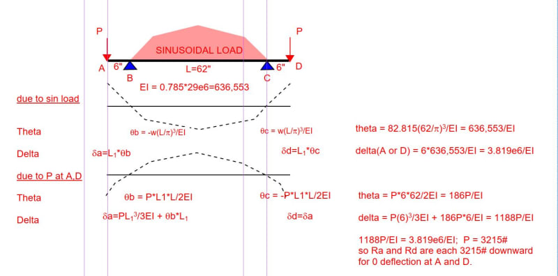
Eliminating supports A and D, Ra and Rd are each found to be 3215# downward for zero deflection at A, B, C and D. This is in agreement with Doug's result.

Capture_n69zdj.jpg
 
BAretired:

One word: Elegant.

I had all the pieces the first time I looked at this but could not see the forest for the trees.

Thank you.
 
Well, actually, I had an error in the expression for theta due to Ra and Rd (missing a 2 in the denominator), so you would not have got the correct answer the first time around. We seniors have our good days and bad days.
 
My calculations from 1st principals gives Ra = -3214.9 lbf and Rb = 4849.9 lbf. This is the same as other posted results.

The method was based on M/EI. The boundary conditions were zero gradient at mid point of beam and zero deflection at Rb. Both resulting equations were functions of Ra and Rb. The gradient at Ra was substituted into the deflection equation. The second equation was vertical force equilibrium. It seems to work!
 
Back
Top