Continue to Site

Eng-Tips is the largest engineering community on the Internet

Intelligent Work Forums for Engineering Professionals

  • Congratulations KootK on being selected by the Eng-Tips community for having the most helpful posts in the forums last week. Way to Go!

Structural Calculation of Guard Rail 3

Status
Not open for further replies.

PYA92130

Civil/Environmental
Oct 2, 2023
6
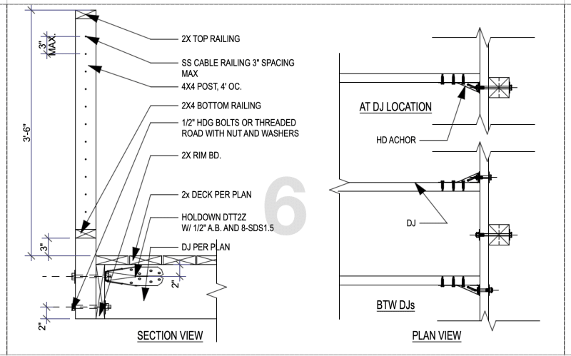
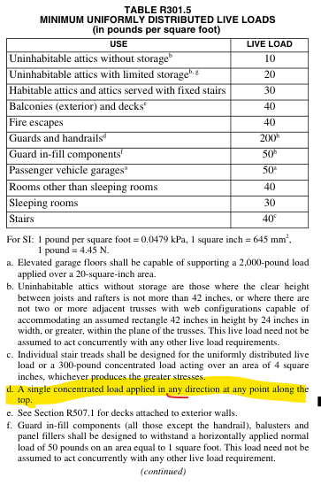
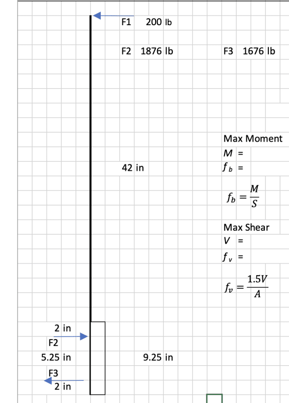
I have designed guard rails based on the AWC prestige method. However, City plan checker want me to provide a structural calculations to show it meet 200lb concentrated load. However, when I treat both bolt as point of support, I got some larger load due to moment. I think I must wrong in the beginning. but I can't figure out yet.

Anyone can help me?

Screenshot_2023-10-01_at_10.23.59_PM_kopq9n.png
Screenshot_2023-10-01_at_10.25.00_PM_semih5.png
 
Replies continue below

Recommended for you

I would potentially make an argument that your lever arm could be 6", due to the fact that compression won't be transferred through the bolt, but rather post bearing directly on the wood.

Edit: made a calculation error in the last post. Tension using a larger lever arm taking into account post bearing gets a tension around 1624 lbs.

Using your 5.5" I get a similar answer to you.
 
Unfortunately, your math is correct.

Is there any chance your 2x top rail is strong/stiff enough to distribute the 200# load to surrounding posts?

Please note that is a "v" (as in Violin) not a "y".
 
WinelandV said:
Is there any chance your 2x top rail is strong/stiff enough to distribute the 200# load to surrounding posts?

That is typically why i use a 2x6 cap. Also, gives a better target for a beer.
 
I feel like you should use a double band as the bending in the single where it does not align with the connectors could be a theoretical issue.
Also, if you call out a DJ, show a DJ. Do you really need a DJ?
 
I feel his DJ nomenclature stands for deck joist, not double joist.
 
Your math looks correct. I agree with jayrod12 that you might be able to increase the lever arm considering the compression force won't go though the lower bolt.

Overall, this is a good detail. Following are a few additional observations/comments for discussion:
[ol 1]
[li]Perhaps this isn't a design consideration, but it's likely that the bearing stress between washer and post exceeds the perp to grain stress of the wood.[/li]
[li]Another minor concern, but the distance between the two bolts should not exceed 5" per NDS requirements. This is to limit splitting potential due to cross-grain shrinkage of the ledger. The 5.25" that you have is probably fine, but technically the code says 5".[/li]
[li]Maybe you can distribute loads between adjacent posts through the top rail as noted above, but in that case, you need to consider what happens where the rail is not continuous.[/li]
[li]I don't think this is necessarily realistic and I've never heard of anyone accounting for this, but just for discussion it's interesting to note that the 200 lb concentrated load is required to be applied in any direction. Technically, the connection should also be designed to resist the 200 lb force pulling inward.[/li]
[/ol]

EDIT: I see that a number of the posts just before mine beat me to the punch on a few of these.
 

The new NBC for Canada addresses that with a reduced load requirement for 'pulling'. A couple of decades back, on a project, due to edge distances issues, I had to use that to provide a 'guard' design.

-----*****-----
So strange to see the singularity approaching while the entire planet is rapidly turning into a hellscape. -John Coates

-Dik
 
DTT2Z capacity will work after you change the moment arm distance? You can also use 2X12 joists? I always use 2x12 on my projects.
 
What's "Prestige method?"


These are structurally tricky, and I'll also point out that the AC for these components omit the substrate connections even still it doesn't even meet the ASTM because it allows like a 45° angle to the applied load, unless they changed it. You seem to be applying the actual code, rather than the reduced AC load that the guardrail folks test to.

Regards,
Brian

ETA - that detail "away from the deck joist" is going to put a great deal of torsion on the band joist, and I don't know of any allowable stress for that. If I recall, the Loferski/Woeste testing found that framing to be unworkable. If you really wanted to go that route that would be where you'd require in-situ testing.
 
Thanks for everyone help.

@Eng16080, you are right, I need to limit to 5" bolt spacing even 5.25 is very closed.

@Doublestud. DTT2Z won't work if block is 2x unless I switch to 2 2x. in this case, I have to switch to HTT4.

@Jayrod12, thanks, I will adjust level of arm to 6". However, my question follow will be if 200 lb is pull direction instead push outward. then low bolt is experience tension, Am I right?

Thanks again everyone.

 
Correct, for the pull situation the lower bolt would be the governing bolt in tension, but I again would argue that bolt is 7.25" from the top of joist, therefore your lever arm is closer to 6-6.25" since it will push on the wood and not the upper bolt.
 
is your top and bottom rail designed for the compression from the tensioning of the cable rails? that force is generally not insignificant. Without that you will have a nasty moment in the plane of the railing at the end posts. You will have bending of the end post regardless. I usually see 200-300# per cable, so maybe 1200 plf at the end post.
 
lexpatrie, In the first article that you linked, it seems that the author is confusing the 200 lb concentrated load required by the code with the 500 lb test load. My understanding is that the 500 lb test load is to verify that the 200 lb load per code is being satisfied. Interesting article.

PYA92130, If you're designing for the pull condition as well (which we probably all should be), then you'll need an additional DTT2Z or some other means to transfer the tension load from the lower bolt into the deck framing.

Based on this thread, I'm going to revise my standard detail for this connection. I'll post the revised detail when I get a chance in case it's of use to anyone.
 
Where is the beam supporting the joists? Does the architectural drawing really show the posts are sitting at the end of the deck? So your deck floor stops before the posts?
 
Personally, I think 200 lbf is ridiculous for non-industrial applications.

I posted to the ASCE forum a while back and got crickets except from Ron Hamburger, whom I have a lot of respect. He spent the time to dig up the testing that was done in the 70s, on behalf of OSHA to come up with this criteria. A 200 lbf is me hitting the top rail at over 1.0g with a LDF of 1.0, which is ABSOLUTELY ridiculous. Not too long ago, we could use 1.33, but that was taken out when the code further defined the force as a live load, not a transient load.

I am always embarrassed when I present guardrail details to my clients. There is apparently no pushback from the engineering community due to some of the recent rail failures, which I'm sure, that are the result of either dry rot or not designed at all. Also consider the fact that the deck joists will not always be at 4'-0" centers, so you will have to come up with a Rube Goldberg detail for the case where the post does not align with the deck joist. Another condition to look at is at the corners. Hopefully, you could trib some of the load to the top rail connecting to the exterior building wall, but, if not, good luck! Even so, you have to detail/analyze the 200 lbf parallel to the long direction of the deck. Yes, there are many posts to take the load, but detailing that connection at the corner, providing proper edge distances for the bolts, etc. is always challenging.

Here in California, we have CA SB 721 and SB 326 coming up where we are going to have to look at a lot more rails between now and the end of next year. As soon as a contractor finds dry rot and needs to present an engineered detail to the local jurisdiction, we are going to become Enemy Number 1 if we follow the code explicitly.
 
I forgot to mention a detail is required for the condition where the joists are parallel with the top rail unless the deck is no more than four feet wide.
 
SE2607 said:
A 200 lbf is me hitting the top rail at over 1.0g with a LDF of 1.0,

Just thinking out loud, but maybe the 200# is a backwards way to enforce a specific level of stiffness on the guardrail. Granted that doesn't change the fun forces and detailing that arises from >700#-ft reacting at the base of the guardrail.

Please note that is a "v" (as in Violin) not a "y".
 
Status
Not open for further replies.

Part and Inventory Search

Sponsor