Eng-Tips is the largest engineering community on the Internet

Intelligent Work Forums for Engineering Professionals

Structural Calculation of Guard Rail 3

Status
Not open for further replies.

PYA92130

Civil/Environmental
Oct 2, 2023
6
0
0
US
I have designed guard rails based on the AWC prestige method. However, City plan checker want me to provide a structural calculations to show it meet 200lb concentrated load. However, when I treat both bolt as point of support, I got some larger load due to moment. I think I must wrong in the beginning. but I can't figure out yet.

Anyone can help me?

Screenshot_2023-10-01_at_10.23.59_PM_kopq9n.png
Screenshot_2023-10-01_at_10.25.00_PM_semih5.png
 
Replies continue below

Recommended for you

WinelandV - The majority of the stiffness is derived from the cantilevered post, the rotation at the base and slop of bolt holes if using bolts, not lags or SDS screws. The issue I have is with all the hardware that is required to transfer that force into the deck members. To me, being able to use a C_sub_D of 1.6 would make things more realistic and not affect the stiffness.

Side note: I really wish I knew how to quote posts on this forum. It's probably easy, but it's difficult for me to see the obvious :).
 

being sarky? Just curious...

-----*****-----
So strange to see the singularity approaching while the entire planet is rapidly turning into a hellscape. -John Coates

-Dik
 
Somehow, we went from a 200# ultimate load in OSHA to a 200# live load in ASCE 7. Is there a significant history of properly designed guards failing at 200 pounds? I doubt it.
 

With the Millenium tower incident, you might do a re-think...

-----*****-----
So strange to see the singularity approaching while the entire planet is rapidly turning into a hellscape. -John Coates

-Dik
 
dik said:
With the Millenium tower incident, you might do a re-think...

I'm not totally up to speed on this project, but isn't he part of the solution, not part of the problem?

If not, please enlighten me.

Even if this project puts a black mark on his resume, Ron Hamburger has done more for this profession than just about anyone else, particularly those who spend much of their non-billable time, including me, on non-consequential posts on the Internet.

No re-thinking required by me.

ps - Thank you, ProgrammingPE!
 
or maybe the cause of it. catch thread thread815-490007

-----*****-----
So strange to see the singularity approaching while the entire planet is rapidly turning into a hellscape. -John Coates

-Dik
 
dik said:
or maybe the cause of it. catch thread thread815-490007: SF Tower settlement Part III

I'm sorry, but I'm not seeing where HE is the cause of the problem. So far, to me, it seems the cause might be the original pile design were friction piles instead of end bearing piles.
 
Back to the topic at hand, please.

What is this AWC "prestige method"?

Eng16080 - Speaking from recall here, but the Loferski/Woeste articles use the 500 lb test load because it's "not engineered" rather it's in-situ testing per Chapter 17 of the IBC. It's not confusion. They do the same thing with ledger testing in a different article. Guertin refers to that testing and states:

"Much of the recent discussion about deck railings originated with the article ("Strong Rail-Post Connections for Wooden Decks") that detailed testing done at Virginia Tech of several typical post-to-joist connections. To design the test, the researchers first looked to IRC Table R301.5 (Minimum Uniformly Distributed Live Loads) and footnote "d," which require the guard to support a 200-pound concentrated load at any point along the top. Then they applied a safety factor of 2.5 - required by IBC section 1714 (Preconstruction Load Tests) for any tested assembly - and came up with a 500-pound test load."

Regarding duration of load - While there is room for argument, the code (as mentioned by others) dictates it as a live load. The in-situ testing requirement is for the load to remain in place so a duration of load ("in design") has at least some justification, 10 minutes is probably too aggressive, (I'm actually picturing a construction load with a stack of heavy sheet material leaning against it, not an occupant induced load) but perhaps the 24 hour DOL would be justifiable. I wouldn't use it, and haven't, but there is at least some reasoning to using a duration of load above 1.0 (note this directly contradicts the intent of the code, however, your E&O may vary). I would also point out that using that duration of load adjustment might upset your E&O provider as they may elect not to defend your "defective work", (you did deviate from established engineering practice, after all), and from a more pragmatic standpoint, if you use a higher duration of load, I'd specify in-situ testing after the fact to ensure the level of construction meets your design (loading rate should be considered in the test setup).

Regarding a post that doesn't align with a joist and somehow getting it to calculate out, well, add a joist.

As to "rational analysis" .... I don't quite follow the 6" lever arm but. While a force at the CL of the bolt makes sense, it sounds like some people presuming the full compressive load is taken at the absolute top of the joist or even the plank (i.e. if the bolt is 2" from the bottom of a 2x10, the lever arm is 7.25"). This is an unrealistic stress distribution and the actual lever arm for the M/d calculation should be adjusted at least based on an appropriate (linear, rectangular) stress distribution, a la how base plates are done, masonry allowable stress/strength design, etc, into the compressive bearing on the wood ledger, or ignore the band joist compression perpendicular to the grain crushing/bearing and design CL to CL of the bolts, you are conceding the band joist will crush which will affect the deflection calculations but you are providing a valid load path (after band joist crushing).

IBC_1604.4_rational_analysis_fbrfbl.jpg


I don't think the Loferski/Woeste testing established that deflection is an issue, it's handling the load/strength/life safety aspect that's controlling their revisions. Testing in that case probably demonstrates that the crushing of the band joist does not cause the as-built to violate the deflection limit.
 
Hi, everyone, thanks for your great responses.

if one of bolt has tension around 1876 lb, with 1/2" bolt and washer.

Assumed I use DFL no1. f'c perpendicular to grain is about 419 psi after factor adjustment. my logic tell me I need to pick up washer bigger enough to pass the pressure to wood itself. that mean I need 1876/419 = 4.5 square in washer? That is really something I never saw in the field. However, that is what math told me.

Did I do something wrong here?
 
lexpatrie: thanks for getting this discussion back on track! Regarding my comment about the article confusing the 200 lb and 500 lb loads, what you wrote makes sense, but I was referring to:
First Article said:
Since the "Strong Rail-Post Connections" article appeared, I've heard a lot of discussion among deck professionals about whether guardrails need to be able to support a load of 200 pounds or 500 pounds. I've adopted the higher standard because other code provisions, referenced standards, and International Code Council Evaluation Service (ICC-ES) test criteria for manufactured guardrail systems all seem to support it.
This makes it sound like there is discussion concerning using a 200 lb load verses 500 lb, but the two are the same with the latter not including the safety factor. Or am I missing something? I only skimmed the article, so it's possible.

Concerning the load duration factor, you raise an interesting point. Using CD = 1.0 seems safe, but getting a connection to work will likely be very difficult. Personally, I'm torn on what to use and how to ultimately create my own detail for this condition. The "Prescriptive Residential Wood Deck Construction Guide" by AWC uses CD = 1.6 for their connection details. Also, the load rating for the Simpson connectors used in the detail here also assumes CD = 1.6. Per NDS Appendix B, using CD = 1.6 essentially means that the total duration of the loading on the post is limited to 10 minutes over the span of 10 years, per my understanding. Is this reasonable? I'm not sure.

I don't think the compression component of the moment will go through the lower bolt. It will be transferred to the rim board due to direct bearing.

PYA92130: Per my comments further up, I also noted that bearing on the washer could be an issue.

EDIT: Also, is using DF-L No.1 accurate? I'm from the Northeast and PT lumber around here is all Southern Yellow Pine No. 2.


Regarding using a load duration factor, CD, equal to 1.0 for this connection, while I understand (and possibly agree) with the logic, what does the connection detail look like in this case? For example, per this assumption, the detail presented here doesn't even work with a standard 4x4 post (per my quick calcs.) Nor does the holddown work.
 
lexpatrie, Eng16080 and others commenting about using a CD of 1.0, ASCE 7-16 section 4.5.1 is pretty clear that the handrail/guardrail load of 200 lbf is a live load and, as such, warrants a CD of 1.0 much to my displeasure. I think it's ridiculous. Since I no longer have to spend every waking hour as billable hours, this (as well as directional wind loads in lieu of envelope on C&C elements such as ridge beams and hip beams with TA < 700 SF) was the main reason I renewed my ASCE membership. However, the response I got on both issues were basically no more than crickets, so my enthusiasm waned. Now, I just tell my clients I find the guardrail connections embarrassing and say there is nothing I can do about them. Pretty sad.
 
Still wondering what "prestige method" is.

(I'm not trying to beat anyone over the head here, but I have trouble with concision and I'm trying to be detailed and provide the background logic as well, as we all know, the foundation of an argument can be a weak point just like a foundation of a building can be a weak point, so here's the philosophical/metaphysical "load path").

A brief detour - (it's topic adjacent, at least, but it's background on part of my reasoning here, as well.)


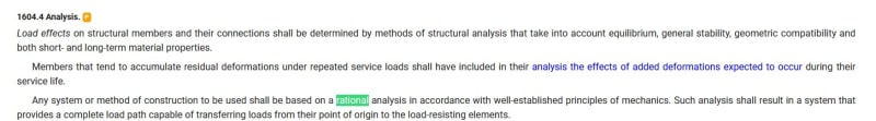
I'll try to paraphrase, or perhaps state what it means to me, not quite paraphrasing. If you provide a complete load path that works, via satisfying equilibrium, (rational analysis, complete load path, well-established principles of mechanics) the actual failure load will be at least this path, possibly higher, i.e. the design is safe. This is partly what I'm getting at when I suggest going "around" the perp to grain "bearing" on the band joist. While the band joist may crush, If there's a bolt there that can take the load, if the band joist gets compressed/crushed, the bolt can provide a safe load path, after. That what seems to have happened in the Loferski/Woeste testing as well.

Going slightly farther, (I like to cite examples a lot) at least one of the Woodworks examples has a great deal of wood crushing involved in shear walls for seismic/wind, crushing load on wood isn't exactly a failure, it's intended to limit deflections, and at least partly is there to prevent cracking damage to finishes, which doesn't quite sound like life-safety to me, and it seems at least some in the structural engineering community take crushing into account in strength-level drift checks for seismic but do not restrict a design to "below" the crushing load on the plate.


Back to the topic, (more specifically)
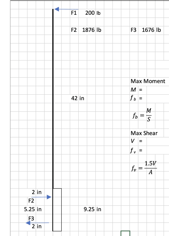
PYA - is that the compression perpendicular to grain load on the 4x4 post, then, due to the bolt tension? I don't think I've personally seen such a plate, but it seems justified by calculation. Alternately an oversize washer versus a USS could be specified and would offer some additional area versus the full size plate washer.


Testing/Engineered design loads

Eng16080 - I'll have to re-read it.

Ok, here's what I came up with. Some of these JLC folks are professional engineer/builders, some are not. I don't usually dig into that because I'm reading the article for theme/overview/comprehension, not to adopt the details as a P.E. - a) Mike Guertin doesn't claim to be a professional engineer ( the comment involves "deck builders", i.e. not professional engineers. So if it's a random hacked together mess, the 500 pound load applies. [BECAUSE it's done without a professional engineer's seal and isn't already tested, AC still doesn't address substrate attachment, neither does ASTM as far as I know]. I still dislike the AC because it allows that load angle, so to me that procedure doesn't even meet the code (Code points to/references/adopts ASTM, ASTM is 200 pound point load in any direction). So. To me they are the same load, the 2.5 comes from Chapter 17 (1709.3, load test procedure not specified), the 200 comes from code/ASTM (1607.8.1.1).

If you're trying to engineer (and seal) the connection the 200# would apply, if it's some random hack together method (non engineered), then it's in-situ and the 500 would apply, that'd be my answer. If you engineer it for 200 lbs and feel uncertain, in-situ testing (for 500 lbs) would validate it as acceptably safe, (even if it didn't quite calc out?). I mean, that's what Loferski/Woeste did?

Duration of load

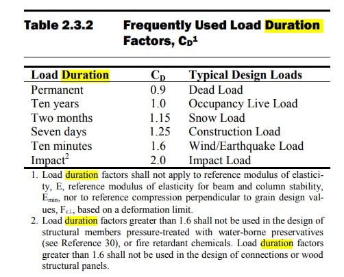
There's an old 1.33 for wind/seismic mentioned in the 1997 NDS commentary. Wind/earthquake now is 1.6. While 1.6 is ten minutes, again, given the TERM on duration of load, and the Section in the code (Live loads), I hesitate. I'm fairly sure we aren't designing for a ten minute earthquake (three second gust?) but that's the duration in the code.... and it's not actually germane to the discussion here. But there would be either seven days or two months as alternatives....

NDS_2018_Duration_of_Load_ufqqnp.jpg


1.6 is like ten minutes, something between say, 10 years "Live" and 24 hours (ins-situ test duration in Chatper 17) is more justifiable?

As far as being conceptually torn on duration of load, I feel that. I do. But without going down the whole calculation path for various scenarios, I wonder if 1.33 or 1.25 or 1.15 does you all that much for the design, wood is offered in discrete sizes, after all.

Given my normal approach (measure twice, cut once, and what would an adverse engineer say in a failure analysis/board investigation vis-a-vis life safety), I'd design for CD = 1.0. Duration of load of 1.0 is REALLY defensible as appropriate, i.e. five out of five dentists.

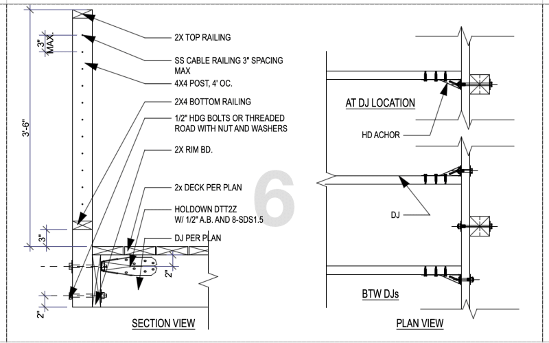
You raise an interesting point with the duration of load used in the prescriptive guide, however, I was unaware of that tidbit. Also note that the DTT2z (shown above in the OP's detail) "allowable load" on the brochure is based on a 1.6 duration of load. I hadn't noticed that, either.

If you use Simpson products for loads other than what they were developed for, usually crossing from one duration of load to another (lower Cd, allowable load pro-rated downward), and would always check with them first. I would generally expect you can factor them down/up PROVIDED they have different values for the various duration of load that are listed for the product (i.e. roof uplift ties). If the loads don't change based on duration then they are nail limited and you won't get an increase/decrease, i.e. it's not legit to factor them based on duration of load, as I recall.

Load path - bolt or band joist crushing

Granted, either design approach is valid so long as it is justified by statics (see above), my suspicion is that the bearing/crushing approach will severely limit the design. Fc perp doesn't have a duration of load in it.

Wood species - DF or SP

This is an EXCELLENT point. West coast tends to have DFL as their default treated lumber. PPT DFL is INCISED, by the way, that will affect the design (including Fcperp), I've seen it elsewhere, but I think it's specified on drawings by West coast folks. I'd also mention the propensity for "green" lumber out west, there are more issues here involving drying shrinkage. Otherwise, pressure preservative treated wood (for exterior uses) tends to be Southern Pine #1/#2, you can "confirm" by checking your local Home Depot and looking like a lunatic searching for a grade stamp.

Not sure that is an exterior guard in this case, but it seems likely.

Side note for OP - "Threaded ROAD" (you mean rod).

ETA - SE2607 - prescriptive details and/or in-situ testing (or, rather, both) are an option.

Regards,
Brian
 
Status
Not open for further replies.
Back
Top