Continue to Site

Eng-Tips is the largest engineering community on the Internet

Intelligent Work Forums for Engineering Professionals

  • Congratulations KootK on being selected by the Eng-Tips community for having the most helpful posts in the forums last week. Way to Go!

Surface Profile and Size 2

Status
Not open for further replies.

AMontembeault

Mechanical
May 13, 2014
26
I'm looking at a series of prints which detail a round feature of size, controlled by a datum-less surface profile. My question is, should the diameter be basic, or limit toleranced?

My inclination is that it should not be basic - that a datum-less surface profile is just a form control (in this case, no different than circularity or cylindricity), and profile must be used as a refinement of an independent size tolerance, as described in ASME Y14.5-2018 section 11.2.

That said, I have doubts, because I often read, even in this forum, that size is controlled, and I look at Figure 11-10 in Y14.5-2018, and all of the size dimensions are basic and the all over surface profile has no datums.

What nuance am I missing?
 
Replies continue below

Recommended for you

Your diameter should be basic. With or without datum feature references, profile controls form and size. The only way to release that would be with the dynamic profile modifier in Y14.5-2018.

Its right there in the first sentence of the paragraph 11.2 that you referenced "Profile tolerances are used to define a tolerance zone to control form or combinations of size, form, orientation, and location of a feature(s) relative to a true profile." Orientation/location depend on datum references and other features (ie: in a pattern). Size and form do not. The portion which you referenced says WHEN it is a refinement of size of a toleranced dimension ie: fig 11-32
 
You might miss this: "Profile tolerances are used to define a tolerance zone to control form or combinations of size, form, orientation,
and location of a feature(s) relative to a true profile"
 
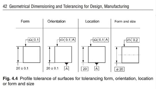
Profile controls what you want it to control:
Profiles_poemmy.jpg


"For every expert there is an equal and opposite expert"
Arthur C. Clarke Profiles of the future
 
CH,

Noooo…..Not again this "less than good" picture:)
G. Henzold

I do not think this author is aligned with the ASME's teachings or the letter of the law.

 
The diameter can be either basic or directly toleranced.

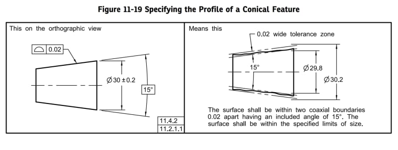
Fig. 11-19 shows a surface of revolution where the feature must meet size limits as required by the +/- tolerance, and its form is controlled by the profile tolerance. See below.

The choice is according to what roles you want to assign for the profile control. I agree with CheckerHater.

20200624_190205_utksmw.jpg
 
I just want to say that the second picture from the left (CH's figure) -Orientation- is less than robust. I do not like it, nor use it. Period.
Is the author's (G. Henzold) opinion about correct usage within ASME's rules and regulations. G. Henzold is a known authority, but he is one of several known authorities in the GD&T community who don't all agree with each other.
Plus, the book is an old book (written, I assume, in some agreement with 1994 version of Y14.5). In the meantime some things have been clarified (even similar examples have been removed from 1994 standard) and some of them not.

Burunduk's pictures are for a cone (not a FOS within Y14.5) so anther story altogether.

Burunduk,
Using strawman arguments does not work either.


Interesting enough Burunduk's picture in the 2018 draft used dynamic symbol and had Ø30 basic.
0.2 upper tolerance zone and 0.02 dynamic symbol tolerance zone.
Again Ø30 was not plus/ minus, but basic.

A more robust definition in my point of view.

I guess the committee changed their mind in the last minute....before releasing the 2018 version of Y14.5.


Burunduk,

I was trying to avoid including the problematic conical figures. I think you'll find that the true profile in that case in fully defined by the basic included angle - the OP clearly asked about a round feature (assumed cylindrical or less likely spherical, I highly doubt by "round" OP meant conical). While I don't know that theres much in the way of purely technical/geometric restrictions about defining a true profile with directly toleranced dimensions*, there is according to the letter of the standard.

*Though the distinction of how the directly toleranced dimension refers to size requirements (imperfect) vs. the subset of perfect features of variable size defining the true profile might be problematic.
 
OK, so expanding on the idea then, if the dimension isn't called out as a diameter, but as a radius instead, and that profile isn't over the entire surface, but on a unit basis (for example, a note saying that the profile applies in any 45 degree segment, should the radius be basic? Can we say size is controlled if we aren't specifically calling out diametrically opposed points?

In a practical sense, there is no guarantee that any measurements of the radius would all share a common origin (particularly if one is inspecting via a radius gauge). I can accept diameter as basic, because a feature of size is specified, but radial segments seems hinky.
 
There is nothing wrong with CH's (Henzold's) second graphic. Why is there this persistent idea that profile of a surface, when related to a datum, MUST control the location?
In other words, why is it "less than robust"? It's still a true profile.

The cone given in Burunduk's post is the one of two exceptions where the diameter need not be basic (the other being the dynamic profile modifier), and that's because there is no datum at the end of the cone to tie down the translation of the tolerance zone. So the profile is applied to a true profile, but the true profile and its zone can be adjusted left/right until you find it overlaying the part.

John-Paul Belanger
Certified Sr. GD&T Professional
Geometric Learning Systems
 
J-P,

There are many threads here on eng-tips about "profile and ±" combo. Again, the GD&T community is split between camps regarding this issue. You happen to be in one camp, me in the other.
All the others feel free to chose or stay neutral:)
 
OK, so expanding on the idea then, if the dimension isn't called out as a diameter, but as a radius instead

I wouldn't do that. If basic, it wouldn't make a difference if called out as a radius. If directly toleranced, it would be problematic to define anything but a fillet as a radius - even outside of its combination with a profile tolerance.

profile isn't over the entire surface, but on a unit basis (for example, a note saying that the profile applies in any 45 degree segment,

Doesn't change anything. Your diameter should still be basic as it defines your true profile, whether you are talking about 360 degrees or 45 degree segments.

Can we say size is controlled if we aren't specifically calling out diametrically opposed points?

No.*

Side note - what about radial segments seems "hinky" ? Is it the way they are specified (as per your previous thread or something else? If the former I agree. Its also interesting that you asked again here about datumless profile controlling size, I thought I had some deja-vu. [upsidedown]

*[sub]Theres some wiggle room here, if we talk about directly vs. indirectly opposed but I'll try and keep the answer simple for your purposes to not confuse the issue further.[/sub]
 
Yes, greenimi, and obviously I was a frequent voice in those other threads. I only pushed back here because you brought up a disagreement with CH's graphic in this thread.
No need to rehash everything here, but I'll merely say this: Isn't it strange that we have a simple way to control orientation of a flat surface (parallelism), yet if that surface is slightly curved (by design) then there is no similar way to control its orientation?

John-Paul Belanger
Certified Sr. GD&T Professional
Geometric Learning Systems
 
Just to add - I think the crux of the issue is definition of the true profile. With a single planar feature the true profile (form) is fully defined regardless of whether directly toleranced or basic dimensions are used to locate it.
 
Chez311 said:
With a single planar feature the true profile (form) is fully defined regardless of whether directly toleranced or basic dimensions are used to locate it.

Yes, I agree. That is why I have a problem with the "orientation" picture because the profile in the "orientation" picture has datum A shown in the DRF of FCF.


chez311 -- the curve that I speak of would also be a true profile, fully defined with basic radii (and other necessary basic dims to space apart those radii).
But regarding the OP's issue, I think the crux would not be in the use of profile on a radius, but the way it's measured -- he mentioned a radius gage and its failure to check elements of the radius to a common center.

John-Paul Belanger
Certified Sr. GD&T Professional
Geometric Learning Systems
 
greenimi -- I'm sorry to push the point here, but the idea of true profile is completely separate from the idea of a datum reference in a profile FCF.
The flat surface has a true profile, as chez311 mentioned and we both agree. That's all that's needed when it comes to "true profile."
Adding a datum doesn't mean that the relationship to the datum must also be basic; that depends on whether we want the true profile to be oriented, or located/oriented, to the datum.

John-Paul Belanger
Certified Sr. GD&T Professional
Geometric Learning Systems
 
Belanger said:
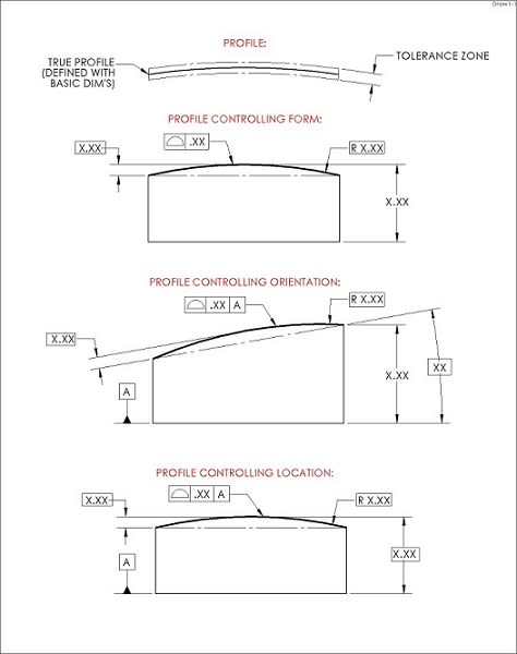
Isn't it strange that we have a simple way to control orientation of a flat surface (parallelism), yet if that surface is slightly curved (by design) then there is no similar way to control its orientation?

Exactly the thought I had when coming up with this picture some years ago:

Profile_2_rt4mwq.jpg


:)

"For every expert there is an equal and opposite expert"
Arthur C. Clarke Profiles of the future
 
Status
Not open for further replies.

Part and Inventory Search

Sponsor