Continue to Site

Eng-Tips is the largest engineering community on the Internet

Intelligent Work Forums for Engineering Professionals

  • Congratulations KootK on being selected by the Eng-Tips community for having the most helpful posts in the forums last week. Way to Go!

Surface Profile and Size 2

Status
Not open for further replies.

AMontembeault

Mechanical
May 13, 2014
26
I'm looking at a series of prints which detail a round feature of size, controlled by a datum-less surface profile. My question is, should the diameter be basic, or limit toleranced?

My inclination is that it should not be basic - that a datum-less surface profile is just a form control (in this case, no different than circularity or cylindricity), and profile must be used as a refinement of an independent size tolerance, as described in ASME Y14.5-2018 section 11.2.

That said, I have doubts, because I often read, even in this forum, that size is controlled, and I look at Figure 11-10 in Y14.5-2018, and all of the size dimensions are basic and the all over surface profile has no datums.

What nuance am I missing?
 
Replies continue below

Recommended for you

Belanger said:
I'm sorry to push the point here, but the idea of true profile is completely separate from the idea of a datum reference in a profile FCF.
The flat surface has a true profile, as chez311 mentioned and we both agree. That's all that's needed when it comes to "true profile."
Adding a datum doesn't mean that the relationship to the datum must also be basic; that depends on whether we want the true profile to be oriented, or located/oriented, to the datum.

I agree with you, but if you remove datum A from the profile callout (the primary datum feature A in the profile in the "orientation" picture) would become identical with the first picture, doesn't it?

 
chez311 said:
With a single planar feature the true profile (form) is fully defined regardless of whether directly toleranced or basic dimensions are used to locate it.

Is it?

"3.68 TRUE PROFILE
true profile: the profile defined by basic radii, basic angular dimensions, basic coordinate dimensions, basic dimension of size, undimensioned drawings, formulas, or mathematical data, including design models."

Which of the listed options define the true profile for a planar feature when all you have is a 2D drawing and the feature is not located by basic dimensions?
 
I like CH's latest graphic. The conclusion most would draw is that there could be a 4th picture: The given curve, at a basic angle of zero but with a ± for location, would have its profile legally be controlling orientation without location. That is essentially what the Henzold picture was doing. (I should amend my earlier post to say that the curve I mentioned does have a basic relationship to the datum, it's an implied zero basic angle.)

John-Paul Belanger
Certified Sr. GD&T Professional
Geometric Learning Systems
 
greenimi said:
I agree with you, but if you remove datum A from the profile callout (the primary datum feature A in the profile in the "orientation" picture) would become identical with the first picture, doesn't it?
Yes. But I'm not sure why you bring that up. (Similarly, if we take Henzold's 3rd picture and remove datum A and change the basic dim to ±0.1, that would be the same as the 1st picture too! So what?)

John-Paul Belanger
Certified Sr. GD&T Professional
Geometric Learning Systems
 
Burunduk,

None of them are necessary, it is implied by the shape of the feature (a single planar feature is unique in that respect). That is unless you believe you need to attach a basic infinite radius or basic 180 degree angle relative to itself for a planar feature controlled with profile. Do you believe the true profile is undefined or defined by the directly toleranced dimension in Y14.5-2009 fig 8-27 ?
 
J-P said:
I like CH's latest graphic. The conclusion most would draw is that there could be a 4th picture: The given curve, at a basic angle of zero but with a ± for location, would have its profile legally be controlling orientation without location. That is essentially what the Henzold picture was doing. (I should amend my earlier post to say that the curve I mentioned does have a basic relationship to the datum, it's an implied zero basic angle.)

J-P,
This is not to specifically pick on you... As far as I know one of the reasons why position tolerance was developed was to not have to deal with inherent ambiguity of directly toleranced +/- dimensions used to locate features. Why doesn't this seem to be a problem in this "profile applied to curved feature" discussion?
 
chez311 said:
With a single planar feature the true profile (form) is fully defined regardless of whether directly toleranced or basic dimensions are used to locate it.

Burunduk said:

Excerpt from ISO 1660:2017:

capture_2_vvkook.jpg


TEF in ISO is equivalent to True Profile in ASME. This is the type of statements ASME needs to not have this kind of discussions any more.
 
pmarc -- no worries about picking on me... I sometimes have strong opinions :)

What you say is true when dealing with a fully defined curve, thus the curve I mentioned certainly needs more definition... Good point.
So let's clarify where this started: Is there a reason anyone would have a problem with the second picture ("orientation") in that graphic that supposedly comes from Henzold? (There's no issues with GD&T vs. traditional style as far as location goes.)
I see that as identical to parallelism, while others cry foul in that instance. That's why my opinion got sorta strong.
 
In the parrallel thread here there is a discussion about advantages of certain geometric callouts over other callouts from the perspective of their intuitiveness. If the interpretation of the profile callout in the 2nd illustration from Henzold is equivalent to parallelism tolerance, then why choose the non-intuitive option?*

*I know someone might say that there could be another profile tolerance wrt A on the drawing and only profile would enforce simultaneity of the requirements, but let's not take the discussion that far.
 
The wording of Y14.5-2018 paragraph 11.10 is not as strong as I would like in this regard, but the fact that it says that a profile tolerance zone is static is getting "warm" in that the tolerance zone is fixed to the shape of the feature's true profile, as well as the location and orientation of the true profile as it is constrained by the referenced datum features.

If a given datum feature is referenced by a profile tolerance specification then any applicable orientation or location constraining basic dimensions must be included, implicitly or explicitly. The presence or absence of a basic dimension cannot affect what a profile tolerance controls. Only the static (fixed) nature of the profile tolerance zone and the capability of the referenced datum features affects what profile controls. If we allow the presence or absence of basic dimensions to affect what profile tolerances control, then we will have "achieved" the opposite of our objective, because we will have introduced ambiguity into the requirements for profile.

Ambiguity is introduced due to the fact that there are two cases for which it is impossible to know whether a give basic dimension has been intentionally omitted, or instead is just not shown, following normal practice: 1) annotated 3D bodies do not show any basic dimensions. Instead the model is queried to get the needed dimensional information; 2) Basic dimensions of zero distance or angle, and angles of any increment of 90 degrees are not shown.

These considerations about the presence or absence of a basic dimension, along with the desire to have a pure form control for a feature of any shape, are what drove the adoption of the dynamic profile modifier. The profile tolerance zone is no longer static if the dynamic modifier is applied. Differing freedom for a profile tolerance zone can also be added by using a customized datum reference frame. Those are both good methods. Leaving out a basic dimension is not a good method.

Dean
 
pmarc -- certainly I would choose parallelism there. But we're discussing what's legal, so it's more of an academic thing here, and it's good to hear all the various opinions and reasons.
BTW, the first picture is equivalent to flatness, so most of use would use flatness there too.
 
pmarc said:
TEF in ISO is equivalent to True Profile in ASME. This is the type of statements ASME needs to not have this kind of discussions any more.

Then it should be added to ASME as well.
As it is, I don't think I can answer without hesitation on chez311's question:

chez311 said:
Do you believe the true profile is undefined or defined by the directly toleranced dimension in Y14.5-2009 fig 8-27?

I would say that the shape of the surface is defined or implied by how it's shown on the drawing, but with the current definition of true profile, a defined shape is not equivalent to a defined true profile as these are not synonyms. And If they are to be treated as synonyms, then there is no reason to require a basic diameter in the op's case. A cylindrical shape can be defined without basic dimensions.
 
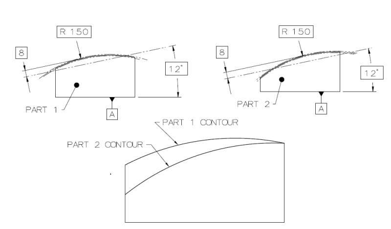
In CheckerHater's last figure there is no orientation control in the image that depicts "PROFILE CONTROLLING ORIENTATION". The inspector doesn't have to align the intersection points between the true profile and the theoretical line that at basic angle with the actual corners of the part. In the image below 2 parts shown as produced, perfectly within the tolerance zone. When overlayed on each other, it is obvious that the "orientation" of the arc can vary.

1593079998763_PROFILE_FOR_ARC_ORIENTATION_a2k3bn.png
 
I lost you here.

"For every expert there is an equal and opposite expert"
Arthur C. Clarke Profiles of the future

 
CheckerHater,
To control "orientation" the way your figure suggests, there should be some kind of a fixed "pivot axis" the tolerance zone can rotate about to the condition that it corresponds to the specified basic angle. For example, the drawing maker could designate the right side face as datum feature B and make the vertical dimension from datum A to the right upper corner basic. Then the profile tolerance would reference datum features |A|B| to create the desired "orientation" control. Even then I'm not sure that could be considered a "pure" orientation control because the height of the feature would also be partially* controlled, with a fully defined location relative to datum A at the right upper corner.

Anyway, considering how it is specified right now, there is nothing that can prevent accepting two completely different features as shown in my sketch.

* Thinking of it, the entire height of the arc along the width of the part would also be controlled. I see no solution for a pure orientation control here.
 
So, you think orientation control creates a tolerance zone rotating around an axis?

Never heard that one in my life.

And what gives you an idea that "The inspector doesn't have to align the intersection points between the true profile and the theoretical line that at basic angle with the actual corners of the part"???

"For every expert there is an equal and opposite expert"
Arthur C. Clarke Profiles of the future

 
Hi All,

I agree with greenimi that there are different camps regarding the mixing of profile with +/-. As long as Y14.5 continues to advocate true profiles defined by basic dimensions, while still showing examples with toleranced dimensions, these camps will probably remain entrenched.

I would say that it comes down to how much you value rigorous definition versus simplicity. The definitions for profile tolerances are quite rigorous, because they take advantage of basic definition and datum reference frames. But many people find profile tolerancing complicated and difficult (especially variants like composite profile and dynamic profile). Directly toleranced dimensions can be easier to understand for a lot of people, but their definitions are not very rigorous. Specifying a directly toleranced dimension introduces specification uncertainty, so that we don't know exactly what the specification means when applied to real as-produced geometry. In other words, we know what it means on the drawing but practical difficulties arise when we try to actually measure it. For example, CH's orientation figure has a toleranced X.XX height, from the base to the intersection of the top surface and the side surface. Measuring this height on real geometry would involve some degree of guesswork.

It's interesting that nobody suggested composite profile for controlling the orientation of the surface. ;^(

Evan Janeshewski

Axymetrix Quality Engineering Inc.
 
CheckerHater said:
So, you think orientation control creates a tolerance zone rotating around an axis?

Never heard that one in my life.

Read again.
I did say "rotate ... to the condition that it corresponds to the specified basic angle". Obviously once the "gage line" which is tied to the tolerance zone (shown at basic 8 in my sketch from the true profile periphery) is at the correct angle relative to datum feature simulator A, the tolerance zone is constrained in the appropriate DOF to the datum or datums and the part can be compared to it. Ever seen how tolerance zone overlay is used with an optical comparator?

The inspector doesn't have to align the intersection point between the theoretical line and arc to the physical corner of the part because the physical corner of the part is not related in any way to the datum reference. The tolerance zone is tied to nothing but the DRF or theoretical geometry (true profile) which also is basically related to the DRF. With that being said if the drawing is poorly defined (like in your figure) I would suggest the inspector do the alignment voluntarily for the inspection to have any value, because of the lack of a robust definition in the drawing.

A solution to make it a pure orientation (and form) control and eliminate the location requirement is to define a movable datum target line on the right side face of the part, at the intersection of the "gage line" and the true profile. Call it for example B1 and reference |A|B| in the profile FCF.
 
Evan -- composite profile would control orientation and location. But what's more interesting here is whether a single profile can control orientation alone (along with form, of course), as in the second portion of CH's first graphic above. I'm guessing you would say yes, although I agree that there would be other issues due to the ± tolerancing.

Burunduk -- You're saying that "part 1 contour" and "part 2 contour" of your graphic will both pass inspection relative to datum?
I don't think "the tolerance zone can rotate about to the condition that it corresponds to the specified basic angle." Rather, the whole point of the basic angle is to lock the tolerance zone so that it can't rotate (at least in the plane of the picture; of course there may be a compound angle going on in the depthwise direction).
 
Exactly!

Basic angle locks tolerance zone directionally, and tolerance zone won't "fly around" any further than +/- tolerance let to.

What exactly is "poorly defined"?

"For every expert there is an equal and opposite expert"
Arthur C. Clarke Profiles of the future

 
Status
Not open for further replies.

Part and Inventory Search

Sponsor