Continue to Site

Eng-Tips is the largest engineering community on the Internet

Intelligent Work Forums for Engineering Professionals

  • Congratulations KootK on being selected by the Eng-Tips community for having the most helpful posts in the forums last week. Way to Go!

Surface Profile and Size 2

Status
Not open for further replies.

AMontembeault

Mechanical
May 13, 2014
26
I'm looking at a series of prints which detail a round feature of size, controlled by a datum-less surface profile. My question is, should the diameter be basic, or limit toleranced?

My inclination is that it should not be basic - that a datum-less surface profile is just a form control (in this case, no different than circularity or cylindricity), and profile must be used as a refinement of an independent size tolerance, as described in ASME Y14.5-2018 section 11.2.

That said, I have doubts, because I often read, even in this forum, that size is controlled, and I look at Figure 11-10 in Y14.5-2018, and all of the size dimensions are basic and the all over surface profile has no datums.

What nuance am I missing?
 
Replies continue below

Recommended for you

Belanger said:
so the wiggle room that I'm allowing for profile and ± tolerancing is only for nominally flat surfaces.

Why?
Sorry for insisting, but if it is ok for nominally flat surfaces, why shouldn't this solution be legitimate?

Or another perhaps more questionable option - keeping the height to the upper right corner toleranced as in the original graphic posted by CH and considering it as the size between "a set of two opposed parallel
line elements". As long as the movable datum target B1 is used and B is referenced as in my proposal, it should prevent the problem and the profile tolerance would define the geometry without controlling the general height of the feature relative to A (setting the "arc orientation" as intended).
 
Burunduk,
Let's start off by agreeing that the second portion of Henzold's graphic is legal, correct, and actually identical to parallelism. I realize that it might not be popular with some, but it is not ambiguous. That's why I'm OK with profile for form/orientation, and ± tolerance for location, on a nominally flat surface.

When we move to curved surfaces, my initial thought was that it should be OK, as CH offered in that graphic dated 24 Jun 20 18:38. But you went to great lengths to show how that would not be acceptable, because of the full-circle idea and the notion that the arc we are sampling could be rotated, thus making its orientation to the viewer seem unacceptable. And thanks for that good discussion :)

Now you have modified that same picture to maintain the ± tolerances for location/height -- and profile for orientation/form -- while fixing the rotating-arc problem. However, I don't think your modifications will work, so I'll still stand by my general statement that you've quoted above.

Here's why I hesitate about your graphic from 26 Jun 20 21:36... Your movable datum target point is meant to help determine the ± height (or correct me if the intent was to have the ± height help determine where B1 is). But datum B is only of use to a callout that specifically references datum B. The dimension with ± tolerance doesn't "know" about datum B; it only works as a direct linear measurement -- so it's good you have the dim origin symbol, but that can't be linked to the distance from the right-hand surface.

In other words, your attempt to find that big dot has the same issues as the classic old-fashioned hole which uses ± location: We can't locate off of two "datums" unless there is a DRF created with priority among the datums.
 
Axym, Dean, pmarc, and all,

May I ask you a somehow unrelated question with the discussed subject, but since you are committee members and you have a strong contribution to the Y14.5 standard development:

Do you think applying flatness to the curved surface in Burunduk's example is legal?
I have a stand alone thread for my question, but I am fine to get an answer here or there too.

I cannot find a definitive statements in Y14.5 to cleary state that flatness shall be applied to a nominally planar surface. Again, I am asking from the theory point of view (academic question).


Dean,
May I ask, why are you measuring the "mating size"? I take 58+/-2.5 as a requirement that the actual local size of the feature in each cross section shall be within the specified tolerance of size. Same for Henzold's graphic. Why is the size requirement in his graphic should be any more ambiguous than any size requirement for parallel surfaces?
 
Belanger said:
In other words, your attempt to find that big dot has the same issues as the classic old-fashioned hole which uses ± location: We can't locate off of two "datums" unless there is a DRF created with priority among the datums.

That's a very good point, thank you for bringing this to my attention - I agree.

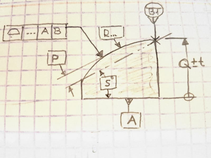
What would be your opinion on the scheme shown in the sketch below? A different modification of CH's figure.

20200628_225736_ubxrsr.jpg


I think that it is pretty straightforward with the dimension origin symbol that the upper right corner shall be located so that no low point on it is below Q-t from a tangent plane of the bottom surface and no high point can be above Q+t from that tangent plane. I say "tangent plane" and not datum A on purpose (naturally, most chances are that the simulated datum A will be used as the tangent plane in practice, but the drawing does not create a bond between the +/- dimension and the datum). If the size tolerance is loose enough (the only case where the entire scheme makes sense), it shouldn't be an issue if the corner comes out relatively sharp or significantly chamfered, it should still be within that 2t zone in its entirety. The datum target B1 shouldn't be accurately coincident with any element of the corner. It is adjusted at height and used as a movable anchor for the profile tolerance zone, to allow best-fitting of the entire arc surface. Thoughts?

And another question:
You said that you are OK with a combo of +/- and profile like in Henzold's graphic, the "orientation" portion, if the surface of the considered feature is nominally flat. Do you mean it is OK if it's nominally flat AND parallel to the datum, or can it also be at some basic angle and with profile acting as angularity?
 
Dean -- I have no idea why in your sketch you would accept a part that has an actual local size of 46.00; your minimum allowed is only 55.5. So the two-envelope dilemma doesn't even exist, at least in the way you portray.

For the "orientation" portion of the Henzold graphic, just swap the parallelism symbol in there. It's as simple as that. (Of course, there is a flaw in that the part is symmetric so when holding the part we don't know which face is datum feature A -- could this be the issue you're getting at?)

But let's dive into the details: If presented with that Henzold drawing, an inspector could first verify the size (height) by using calipers or a similar device to check the actual local size, which shall always be somewhere between 19.9 and 20.1.
Then, still looking at the size requirement, the inspector would have to verify the AME, perhaps with a simple "go" gage of 20.1. This is of course the Rule #1 idea, which is not done away with by a profile tolerance.
Finally, the inspector would check the profile tolerance, which has nothing to do with size. Set the part down on a granite surface plate, which establishes datum A. Then using a height gage, run the indicator across the top, tracing as many elements as possible, and the FIM of the indicator shall not exceed 0.1.
 
Burunduk -- I'm still not quite convinced, even about that newest revision. I'll have to think about it some.
Let me ask two questions: First, can I presume that the movable datum target B1 is a line? (It can't be a point because that wouldn't stabilize the DOF needed for a secondary datum in the FCF.)
Second, what is the purpose of having a movable target there? Maybe we could just label that entire vertical surface as datum feature B.

For your other question, yes I think I would be OK with profile of a surface used to control form/orientation for a nominally flat surface even if it's not parallel to the datum. Similar to what I wrote to Dean about parallelism: take any classic angularity drawing from a basic GD&T textbook (a flat surface angled to a single flat datum), and just replace angularity with profile of a surface; it's the same meaning.
I myself wouldn't do that, but it would not in any way be ambiguous or illegal. So it's just the darned curves and other non-flat surfaces that require extra thought, in my viewpoint.
 
Burunduk and Belanger,

My mistake. Please pardon my "Sunday driver" post. I was forgetting that datum feature A is referenced in Henzold's orientation oontrol example. It seems best for me to delete that post.

As long as the directly toleranced feature is a feature of size, and as long as we can tell which feature is datum feature A by adding a symmetry breaking feature, then I have to agree that it is not ambiguous.

I would still use parallelism for the simple example shown, and I expect the applications that grow from the example will introduce their own ambiguities.

Dean
 
Belanger said:
First, can I presume that the movable datum target B1 is a line? (It can't be a point because that wouldn't stabilize the DOF needed for a secondary datum in the FCF.)

Yes. I didn't show an additional view to depict it as a line but I mentioned in the post where I embedded the first version that it is a line. You are correct about DOF - a point would not be good enough to constrain the rotation about an axis normal to A.

Belanger said:
Second, what is the purpose of having a movable target there? Maybe we could just label that entire vertical surface as datum feature B.

I thought of a movable target line because that's the minimum that is needed to create an adjustable reference to which to tie the intersection line between the true profile arc and the slanted theoretical plane (at basic angle) to prevent the floating which causes the issue.
However, I should have thought about designating the entire surface as a datum feature as you suggest. That makes more sense because it is more straightforward and easier to accomplish in practice. And the intersection of the theoretical geometry should simply be aligned with a secondary datum plane.
Thank you for pointing that out.

So would you agree that if the datum target symbol in my last graphic was replaced by a datum feature symbol applied on the right-hand face, that would be a reasonable way to specify profile for "orientation" (as intended in CH's original figure) of an arc in conjunction with a +/- tolerance affecting the location of the entire feature?
 
Burunduk -- no worries about datum B (full surface vs. target line). I just didn't know if you were using that B1 line as some sort of swivel point or locating point for the arc in question (I don't think it would have done anything regarding that).

Before I accept your conclusion, allow me to "talk out" why the addition of datum B might control the orientation. I'll refer to the earlier picture where you explained how the arc could appear "disoriented" while still falling within the profile zone:
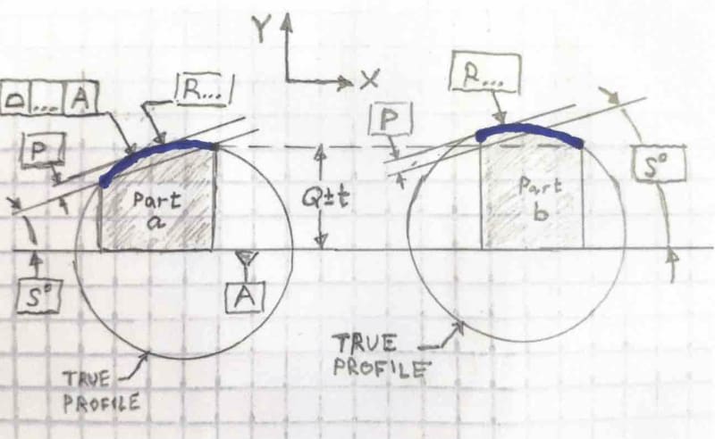
RevisedSketch_o2pjxc_pom7su.jpg


I believe that we accepted that idea -- that both of the blue arcs are within the profile tolerance zone -- for two reasons:
1... There was no way to "clock" the portion of the arc we wanted, since the true profile is merely a radius.
2... Because the axis of that imaginary circle could translate, thus allowing a new portion of the arc to be within the physical boundaries created by the two vertical sides of the part.

Now, by adding datum B it looks like you are eliminating reason #2, and if the axis can't translate left-right, then I suppose it would always force the same portion of the arc to be within the zone.

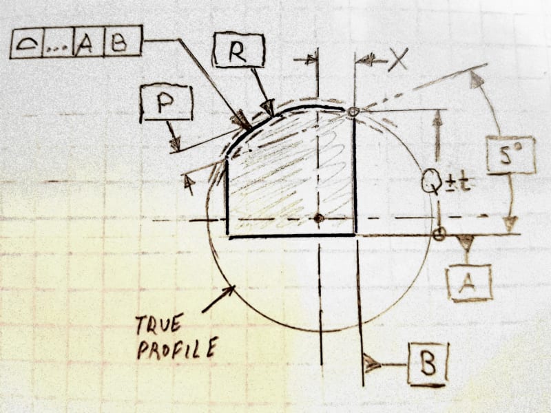
If that's all true, then I would say that your latest graphic would need a basic dim from datum B to the axis of the imaginary circle. The final result: The profile would be controlling orientation from A, and location from B (as well as form).
What are your thoughts on all this?
 
Hi All,

I'm still not really comfortable with this, but I'm not sure exactly why. If the surface was modeled as cylindrical arc that is higher on the right and lower on the left, what allows us to extend it to a full cylinder? Then use whatever part of the full cylinder that we want, to evaluate the feature? It seems wrong, but I can't point to any rules that are violated. If the standard does not disallow this, what would it have to say in order to disallow it?

I will start a new thread to look into this.

Evan Janeshewski

Axymetrix Quality Engineering Inc.
 
In the original construction, were I to tell a person to reproduce it I would say the following:

1) Draw a vertical line of X +/-Y in length.
2) Draw a line at an angle to the horizontal from the top end of the vertical line, down and to the left.
3) Draw another line above and parallel to the second line at a given offset.
4) Draw an arc of known radius tangent to the third line, passing through the top end of the vertical line.

The missing rule is that things that are shown as intersecting are basically intersecting. There seems to be no description for allowing errors in the construction aids used to define geometry.

The alternates seem to assume that the line at an angle can have an arbitrary location with respect to all other geometry. If one is intent in that belief, then there is no other explanation that will serve.
 
Belanger,
I believe that the two reasons you mentioned for two differently "oriented" arcs that would be within tolerance as we agreed are actually one reason. The allowed shift of the true profile axis parallel to the XY plane, even when keeping the height of the upper right corner constant, is what causes the inability to "clock" the orientation of the arc, while different portions of the true profile and tolerance zone can be used to accept the produced geometry.

By adding datum B I am not eliminating one reason out of two, but the entire problem.

Regarding adding a basic dimension from datum B to the axis of the true profile - is it mandatory? Please refer to the following graphic. Would you say that if the basic dimensions R (basic radius), P, and S are known, the geometry is still not fully defined unless you specify X? I would say that a single resultant value of X would be defined for any given set of the other parameters.
20200629_220554_nt8dkd.jpg


axym, we do not have to extend the true profile to a full cylinder. It is enough to use a sufficient arc length of a tolerance zone, larger than the produced arc, to allow different "orientations".

3DDave, drawing instructions are nice but this is not how profile control works. To force the intersection either the right side vertical face should be part of the true profile (by use of the between symbol) or it should be referenced as a datum feature to constrain the theoretical intersection between the slanted plane and the arc to be coincident with a vertical datum plane derived from it. In the original scheme, the profile tolerance doesn't "know" that there should be a vertical surface to the right of the arc (or to the left of it).
 
Burunduck, That's how drafting works. And drafting is the analog to layout of a part. Which is the first step to machining a part. The profile doesn't know anything - the machinist and inspector need to know how to read a drawing.
 
Burunduck.

More to the point - absent the use of FCFs and basic dimensions, no one would ever suggest the results you've depicted as acceptable geometry. And your latest sketch still depends on an understanding that the profile intersects where the construction line intersects the vertical side - an assumption that you find unacceptable when others say the exact same thing.
 
3DDave said:
And your latest sketch still depends on an understanding that the profile intersects where the construction line intersects the vertical side - an assumption that you find unacceptable when others say the exact same thing

To make this understanding relevant to conformance evaluation, there should be a datum reference frame that is able to provide the needed constraints to limit the variation which we are interested in limiting.

Implying the datum reference frame is not how drafting works and guessing it is not how inspection works.

Consider a hole shown on the drawing centered to the width and height of a rectangular prism and normal to one of the faces. The relationship between the hole and all other part features is implied and perfectly clear. Does it mean that we don't need any datum references in the position control? The logic you apply suggests that your answer is yes.
 
As I said, your interpretation is self-serving when you use it to your benefit. There is nothing in the standard that supports your interpretations so far of how to locate the curve.

Your latest sketch still depends on an understanding that the profile intersects where the construction line intersects the vertical side. No datum reference repairs that misrepresentation on your part.
 
3DDave said:
Your latest sketch still depends on an understanding that the profile intersects where the construction line intersects the vertical side.

As I said, for this understanding to be useful the vertical side must either be part of the true profile geometry as part of the considered feature or referenced as a datum feature.

The standard defines that features are located/oriented by datum references that constrain the appropriate degrees of freedom. The only exception I can think of right now is features in a pattern that can only be mutually located/oriented without datum references.

The standard does not specify that "construction aids" can be used as implied datums.

If none of the vertical sides are referenced as datum features and they are not part of the geometry that the profile tolerance controls, the theoretical intersection that is relevant for the profile control is only arc-angle (and it is actually redundant) and not arc-angle-vertical side.


In CH's original example ("orientation" option) the arc and the inclined theoretical plane are basically defined to each other, but the outline of the right-hand vertical surface is neither part of the true profile of the considered feature (the arc), nor it is referenced as a datum feature.

Even if you decide to rely on the inspector's judgment and assume he will try to align the theoretical arc-angle intersection that is part of the definition of the true profile/tolerance zone with one of the side faces to imitate how it is visually depicted on the drawing, there is no way for the inspector to know if the right side theoretical intersection is to be aligned with the right side surface or the left intersection with the left side surface, or maybe some "compromise" between these options should be sought.
 
The right side intersection is clearly defined by the dimension locating that intersection. There is no dimension on the left side. Your example of a datum point depends on finding that exact intersection to define the datum point's location. Unless you don't think that's the case and the datum point can be arbitrarily located anywhere, in which case then your solution fails.

You accept that chamfers can be located from intersections do you not?

It's not an implied datum, a device not mentioned in the standard at all. It's an intersection, which is a device used throughout the standard.
 
3DDave said:
The right side intersection is clearly defined by the dimension locating that intersection.

Directly toleranced dimensions are not part of a true profile definition. A profile tolerance and a directly toleranced dimension(s), when applied on the same feature, work separately and independently of each other, apart from the requirement that "Where used as a refinement of a size tolerance created by toleranced dimensions, the profile tolerance must be contained within the size limits." This doesn't mean that the toleranced dimension "locates" the profile tolerance zone. If the tolerance zone is allowed to float by the DRF and basic dimensions that are applied, it will float independently of whatever the size tolerance controls.

3DDave said:
Your example of a datum point depends on finding that exact intersection to define the datum point's location. Unless you don't think that's the case and the datum point can be arbitrarily located anywhere, in which case then your solution fails

With datum feature B referenced in the profile FCF and labeled with either a datum feature symbol or a movable datum target line, the theoretical intersection is defined to have a relationship with the right-hand surface (to be precise - with the datum derived from it). When the reference is to datum feature A only, the theoretical arc-angle intersection at the right side can float and be at any offset from the right-hand surface (the same for the left-hand arc-angle intersection and the left-hand surface).

3DDave said:
You accept that chamfers can be located from intersections do you not?

I have no idea what are you getting at with this example. A chamfer connects two surfaces and is usually specified with a distance dimension and an angle. If it is controlled by profile then the datum feature references for the chamfer's location are physical features of the part, not theoretical intersections. What do you suggest should be understood as "located from the intersection" in CH's original example, and are you talking about the physical arc-vertical surface intersection or the theoretical one (arc-angle)?

3DDave said:
It's not an implied datum, a device not mentioned in the standard at all. It's an intersection, which is a device used throughout the standard.

If this is how you want to handle this, note that the standard doesn't mention any "construction aids" to which features are supposed to be located. It does cover datum references which are used to define true geometry and tolerance zones by constraining degrees of freedom.
 
Status
Not open for further replies.

Part and Inventory Search

Sponsor