Continue to Site

Eng-Tips is the largest engineering community on the Internet

Intelligent Work Forums for Engineering Professionals

  • Congratulations KootK on being selected by the Eng-Tips community for having the most helpful posts in the forums last week. Way to Go!

Surface Profile and Size 2

Status
Not open for further replies.

AMontembeault

Mechanical
May 13, 2014
26
I'm looking at a series of prints which detail a round feature of size, controlled by a datum-less surface profile. My question is, should the diameter be basic, or limit toleranced?

My inclination is that it should not be basic - that a datum-less surface profile is just a form control (in this case, no different than circularity or cylindricity), and profile must be used as a refinement of an independent size tolerance, as described in ASME Y14.5-2018 section 11.2.

That said, I have doubts, because I often read, even in this forum, that size is controlled, and I look at Figure 11-10 in Y14.5-2018, and all of the size dimensions are basic and the all over surface profile has no datums.

What nuance am I missing?
 
Replies continue below

Recommended for you

If we accept the notion that profile doesn't control orientation in that instance (going by the previous dozen or so posts), and it doesn't control location (because now we're talking about directly toleranced dims), then doesn't it follow that datum A is meaningless there?

I believe if (z) is normal to A and (x) is left and right, then it still constrains orientation in (u). That said, (v) is technically constrained, but the effect doesn't much matter if we assume the extrapolation is possible as shown in Evan's latest sketch.

It seems ridiculous at first glance, but I'm not sure if there is anything in the standard that disallows it. This could occur even if the height dimension was basic.

It might unless the curve was related to the width or vice-versa. The problem is there is a point on either side of the apex of the curve that the distance normal to A is the same.
 
axym,
I created the two parts in the figure by moving the axis of the true profile arc relative to fixed (in the model) side faces of the part, but I suppose it can also be described the way you did and it matters little.
It actually doesn't look ridiculous to me at all and is definitely how a profile tolerance specified that way should work. The so-called arc orientation is the type of variation that profile doesn't control with only A referenced.

Dean,
I am all for basic only dimensions apart of size specifications (for FOS). But the original objective here was to show how a profile tolerance can control orientation without controlling the location of an arc-shaped feature, that is why there is an attempt to keep the height dimension toleranced to locate the feature. I will try to post later a sketch involving "arc orientation" without location controlled by profile and reasonable use of a toleranced dimension to set the height of the arc.

 
axym said:
I would say that the dimension type makes a difference. I wish that Y14.5 didn't do it this way, but the presence of a directly toleranced dimension changes the meaning of the profile tolerance. This is still shown in Y14.5-2018 in Figure 11-32, and they even include the model-based view. If we ignore the fact that it's profile of a line and imagine that it's profile of a surface instead, then it's similar to the second example from the Henzold figure.

Evan,
I know what the standard says/shows. I am trying to say it should not work this way.
 
Dean, here is my suggestion.
I think that the directly toleranced dimension used for location is less ambiguous here than it usually is. Notice the dimension origin symbol and the defined measurement location.
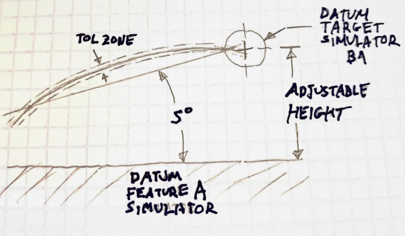
Datum target B1 is a datum target line and it is movable normal to A. Therefore the tolerance zone that is connected to it can be adjusted to correspond with the height of the feature to be best-fitted into it. This way there is no location control by the profile tolerance.

The important thing here is that the basic angle is meaningful in this scheme because there is a defined "anchor point" to which the intersection between a theoretical plane slanted at the basic angle and the true profile must be aligned. This "anchor point" is of adjustable height and doesn't force location.

Drawing:
20200627_001414_rqb6g3.jpg

(Forgot the datum feature symbol for A. It is the bottom face)

Datum feature simulators and tolerance zone:
20200627_001640_ngju4h.jpg
 
Burunduk,

I agree that your approach, using dimension origin (one of those things we have that enables saying the same thing using two different methods :)) avoids the ambiguity associated with a directly toleranced dimension with arrowheads included on both ends of the dimension line.

Why is this better than a composite profile tolerance, or two separate profile tolerances, with one releasing the vertical translation that datum A will constrain by using a customized DRF?

I think datum feature A being referenced by the profile tolerance in your example, then somehow the constraint it provides in the vertical direction disappears when the directly toleranced dimension is added instead of a basic dimension is illogical.

Would it be OK if a cylindrical hole is toleranced with a position tolerance that references a datum feature that will constrain translation in a particular direction, but instead of a basic dimension to locate the cylindrical position tolerance zone in that direction, a directly toleranced dimension is instead specified? If not, then why is the same sort of method OK with profile? If that would be OK, then why would that method be better than using position tolerances to accomplish the same control?

Dean
 
Dean,
I generally agree and there probably are better ways as you mentioned. I just tried to stay as close as possible to the original scheme that was discussed ("profile controlling orientation" in CH's posted figure) which involved a toleranced dimension.

Dean said:
I think datum feature A being referenced by the profile tolerance in your example, then somehow the constraint it provides in the vertical direction disappears when the directly toleranced dimension is added instead of a basic dimension is illogical.

I say that datum A does not provide a useful constraint in the vertical direction regardless of the toleranced dimension, because there is no basic distance dimension in this direction :) (assuming it is a regular drawing and that it isn't supposed to be used with a CAD model for full definition).
 
Dean,
I heard somewhere that origin symbol is called "poor man datum reference frame" as being a compromise between no GD&T and full GD&T = "rich man datum reference frame"

The former could accomplish almost the same thing, but with less headache (and obviously less robustness).
 
aniiben,

Yes, I agree on all points. I've heard an opinion that dimension origin avoids the issue of the supplier not knowing how to handle profile. Then it turned out the supplier had never seen dimension origin before. :)

Burunduk,

Burunduk said:
I say that datum A does not provide a useful constraint in the vertical direction regardless of the toleranced dimension, because there is no basic distance dimension in this direction smile (assuming it is a regular drawing and that it isn't supposed to be used with a CAD model for full definition).

If one of the two basic dimensions needed to locate a position tolerance zone is omitted, then then is the tolerance zone free to translate in that direction, or instead is there just simply a missing basic dimension that needs to be added before the drawing can be released?

I say there is simply a missing basic dimension, and that is the case for both position and profile. I don't think we ever need to/should combine any +/- and profile or position or any other location or orientation constraining tolerance. I think the only place for +/- is for size tolerances and the list of "OK" tolerances that can be applied to non-critical features like chamfers, a radius or spherical radius, counterbore/blind hole depth, and that's about it.

Dean
 
Dean Watts said:
I say there is simply a missing basic dimension, and that is the case for both position and profile.
Dean, if I may jump in... I agree with you regarding position (its need for basics to the given datums), but that's because position's main job is to control location. Profile, however, can play many roles. If profile’s intent is to control location (along with form and orientation), then full basics to the referenced datums are needed. But that's not required for profile -- such as when the intent is to control just form and orientation (see the "orientation" portion of the Henzold graphic which was in the first graphic of this thread).

Having said that, I agree that for clarity, the role for ± tolerances should be limited to size/chamfer/radius. If profile’s intent is to control form/orientation, then the ± tolerances with profile (in the Henzold graphic) are fine because they are size (height) which indirectly controls location.

What I found interesting in this thread is how to interpret things when the profile tolerance is applied to a curved surface, rather than a nominally flat surface. Then, the usage of ± tols (rather than basic dims) seems to be problematic, and I admit that I've wavered from my previous defense of such a practice. But I just wanted to take issue with your blanket statement about profile always needed a basic dim to its datum.
 
John-Paul,

Henzold's orientation example is flawed, because the orientation of the directly toleranced dimension is ambiguous. A size tolerance is oriented to the feature itself, yet many who look at the drawing would instead say that the measurement direction is normal to datum A.

I won't be wavering at all with regard to +/- and profile never being combined. If a datum feature is capable of constraining a given degree of freedom and the basic dimension is missing to define the location and orientation of the tolerance zone related to that constraint, then the drawing is missing an essential element. We have very good ways to altering the constraint of the profile tolerance zone to the DRF and to the feature's true profile now. We don't need to introduce ambiguous elements into the language any more.

We need a logical system that those using MBD and those writing code for handling point clouds of measurement data. Since the presence or absence of a basic dimension is also ambiguous (since, as you know, some are implied instead of shown explicitly) we cannot allow this sort of thing to affect what profile controls.

Dean
 
I agree about the MBD stuff; let's keep that aside and for now focus on traditional-style drawings. Namely, in this case, the "orientation" picture of the Henzold graphic. I'm not sure why you have a problem with that, aside from the fact that parallelism would have been more straightforward.

Dean Watts said:
Henzold's orientation example is flawed, because the orientation of the directly toleranced dimension is ambiguous. A size tolerance is oriented to the feature itself, yet many who look at the drawing would instead say that the measurement direction is normal to datum A.
Datum A has noting to do with the size tolerance or the orientation of the size tolerance. The size tolerance is be handled like any size tolerance of such a flat part, as if datum feature A were not labeled on the print. (I'm of course presuming ASME rules, so we don't get into independency issues.)


Dean Watts said:
If a datum feature is capable of constraining a given degree of freedom and the basic dimension is missing to define the location and orientation of the tolerance zone related to that constraint, then the drawing is missing an essential element.
Not really. Just because a datum is capable of constraining a given DOF doesn't mean that it must, for an FCF that references that datum. Think about the parallelism symbol: The datum referenced by a traditional surface parallelism callout (think of the usual flat block, etc.) is capable of constraining 3 DOF for tolerancing purposes. However, parallelism only uses 2 of the 3 DOF, since the translation/location aspect is not parallelism's job.
Well, the Henzold graphic is doing exactly that: it's simply equivalent to parallelism. There's no need to always assume that a profile tolerance which references a datum must be a location control (witness the earlier mention of Fig. 11-32).
 
I'm not willing to keep the needs of MBD or point cloud software aside. There's no need to combine +/- and profile, so we should not ever do it. There's no need to choose an inferior method.

Dean
 
Dean,
If I interpret your statements correctly, you are for removing fig 11-32 (2018) from the standard, and possibly also this portion of paragraph 11.2, which specifies how profile and directly toleranced dimensions should be combined if one chooses to:

"When used as a refinement of a size tolerance created by toleranced dimensions, the profile tolerance shall be contained within the size limits. For more information on design models, see ASME Y14.41."

Am I right?
 
Dean said:
Yes, I agree on all points. I've heard an opinion that dimension origin avoids the issue of the supplier not knowing how to handle profile. Then it turned out the supplier had never seen dimension origin before.

Yet, it is much less time consuming to tell this type of a supplier (which is very commonly encountered) that the circle that replaces the arrowhead indicates which side of the part is rested on the surface plate when he uses his height gage, than explaining profile.

Many suppliers find it "counterintuitive" :) when you try to tell them that what they measure when setting a zero on a gage of the size-nominal height above the surface plate and then checking points on the upper surface of the part is profile and not +/-. They will end up telling you that profile requires a more expensive inspection with CMM anyway.
 
Since I feel awkward and I am asking myself, why I did not keep my mouth shout (but then we wouldn't get over 70 replies with interesting figures and opinions from all the experts and committee members) I would try to justify why I think 8-27/2009 and 11-32/2018 are sort of bad examples:

Main reason: they are opening the door for (or I would better say: keep the door open) for usage outside of their (figure's) limited scope

Those figure's concepts should (maybe even "shall") be used for rFOS only. And that's about it. Keeping them in the standard creates a dangerous precedent as those figures are used as allowance (OKAY to do so) and arguments to rationalize and usage of combination between profile with ± for a non rFOS. (and that is not too add any MBD issues/needs, keep them aside for now)


Copy-paste from different discussion

"The standard allows the use of +/- tolerances in combination with Profile. You just have to be careful of how/when you do this since, if not done properly, it can be interpreted in multiple legal ways. The example shown in Figure 8-27 in the 2009 version of the standard has only one legal interpretation. The dimension that is toleranced with +/- (the 80+/-0.2) is a regular feature of size (i.e. the "correct" use of a direct tolerance) and therefore is subject to Rule #1. The Profile of a Line callout is then simply refining what Rule #1 would have allowed for that surface. It (the Profile) is essentially controlling the orientation (but not the location) of the line elements on the considered surface relative to A and B. If Profile of a surface were specified in this situation, it would essentially be controlling the parallelism of the considered surface to A (and the reference to B would be superfluous in that case).

But, why control things in this manner if the feature in question does not "act" like a feature of size in its application/function. If the part in Fig. 8-27 always gets biased up against the datum feature A as shown (as opposed to fitting into a slot and being "centered" on the 80mm width), then it would likely make more sense to specify the 80mm dimension as basic and control the considered surface orientation AND location from that datum plane. The figure, though, was not trying to contemplate whatever the truly functional requirements might have been for the part. Rather, it was simply trying to illustrate the theoretical effect of such a callout. It is certainly possible that the requirements as written are the truly functional requirements, so when you state the requirements as shown, then the, "Means this" explanation is correct."

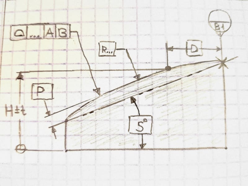
 
Burunduk,

When you asked
Burunduk said:
If I interpret your statements correctly, you are for removing fig 11-32 (2018) from the standard, and possibly also this portion of paragraph 11.2, which specifies how profile and directly toleranced dimensions should be combined if one chooses to:

The answer is yes, I am very much in favor of deleting those portions of the standard. As revisions come along, the use of directly toleranced dimensions to locate features and the combination with profile has been reducing in general. We're just not as far as I think we should be.

So, my arguments are more about how I think the standard should be (and what I think is best practice for current applications) then about what the standard currently says.

Dean
 
Dean,
For what it's worth, I also have my issues with figure 11-32 (and it's 2009 version). First, I don't get why someone would use profile of a line in this case rather than parallelism with the note EACH LINE ELEMENT which does the same thing but more straightforward, as this is essentially an orientation control.
Secondly, I don't like the way the limits of size are represented in that figure. Because of the way it is shown it is perceived as two symmetrically fixed boundaries - 80.2 for MMC and 79.8 for LMC that cannot be violated, with a constant tolerance zone width of 0.2 at each side. However, we know that there is no perfect form requirement at LMC and no fixed 79.8 boundary in reality.
 
pmarc,

Sorry, I misunderstood what you were saying. I know that you are aware of what the standard says.

J-P,

It seems that people are more willing to continue non-rigorous traditional practices in the context of profile tolerancing than with position tolerancing.

I agree that we might want the profile tolerance to only control form and orientation. Perhaps the location of the feature to the datum is not very importsnt and can have a large tolerance. We don't want to specify something complicated like composite profile for something like that - the vendor will freak out! So we specify a directly toleranced dimension to the datum, with a tolerance that is a bit smaller than what the function allows. If there is some ambiguity in what the dimension means or what its measured value would be, it's no big deal because the feature will still function properly. The smaller tolerance buys us additional simplicity in the definition. I see this kind of thing specified all the time, and as we know there are examples shown in Y14.5.

For position tolerances, this approach seems to be much less acceptable. We might have a hole pattern that mounts a mating part, and what we really care about is the pattern shape and spacing and its orientation to the datum. The location to the datum is not very important and can have a large tolerance. We could specify a position tolerance and basic dimensions between the holes, and directly toleranced dimensions to the datums. In fact, this is how it was done in older versions of Y14.5. But not anymore - Y14.5 moved on from this practice decades ago. It's positional tolerancing, so we need basic dimensions to the datums! Composite position would be expected here - few people would think of using plus/minus dimensions to locate the features in this context.

Using directly toleranced dimensions to locate features causes issues, whether it is with position tolerancing or profile tolerancing.

Evan Janeshewski

Axymetrix Quality Engineering Inc.
 
Dean, axym, Belanger,

Seems that the discussion shifted towards dealing with the issue of directly toleranced dimensions specified "to locate features". However, why can't we treat these toleranced dimensions simply as a size specification? Of course, I am not talking about the case of a surface to hole axis distance, but about the distance between physical features, as in the cases discussed.

It is especially simple for fig. 11-32. In my previous post, I mentioned my own reasons for not liking this figure but I don't consider it as an example for a directly toleranced dimension specified in order to locate a feature. Neither the text within the figure nor the paragraph that refers to it suggests that the role of the 80+/-0.2 dimension is to locate the top face. Rather it is used to set the limits of size for the parallel-surfaces feature of size. Although it is reasonable to say that the location of the top face relative to the datum is resultant/derived from the conditions set by the limits of size, it is not a location control in the usual sense.

It is less simple with CH's original figure with the "profile controlling orientation" case. However, can't the directly toleranced vertical distance be considered a size dimension between "a set of two opposed parallel
line elements" (one type of a regular feature of size)?

Personally, I don't think that the directly toleranced dimension is the source of the problem with this scheme as an "orientation" controlling profile tolerance. The same problem I tried to explain and illustrate would occur if the dimension was basic unless there are an additional datum reference and constraint.
 
Burunduk -- I completely agree, and that was the point I was making in my reply to Dean: For the "orientation" graphic in Henzold, the profile lives within a size tolerance. Thus, profile need not control location since the size tolerance would serve as the "location" of the top surface. I understand why some don't like it and want to see the standard changed, but we're dealing with the legality within the current rules.
I also agree that it's different for CH's example of a curved surface, so the wiggle room that I'm allowing for profile and ± tolerancing is only for nominally flat surfaces.

 
Status
Not open for further replies.

Part and Inventory Search

Sponsor