Continue to Site

Eng-Tips is the largest engineering community on the Internet

Intelligent Work Forums for Engineering Professionals

  • Congratulations KootK on being selected by the Eng-Tips community for having the most helpful posts in the forums last week. Way to Go!

Surface Profile and Size 2

Status
Not open for further replies.

AMontembeault

Mechanical
May 13, 2014
26
I'm looking at a series of prints which detail a round feature of size, controlled by a datum-less surface profile. My question is, should the diameter be basic, or limit toleranced?

My inclination is that it should not be basic - that a datum-less surface profile is just a form control (in this case, no different than circularity or cylindricity), and profile must be used as a refinement of an independent size tolerance, as described in ASME Y14.5-2018 section 11.2.

That said, I have doubts, because I often read, even in this forum, that size is controlled, and I look at Figure 11-10 in Y14.5-2018, and all of the size dimensions are basic and the all over surface profile has no datums.

What nuance am I missing?
 
Replies continue below

Recommended for you

Belanger,
My reference to "rotation" was my way to try to visualize the process of establishment of the tolerance zone, not its final configuration.

See for example fig. 6-8 from Y14.5 (see below). One way to describe the establishment of the tolerance zone for the axis is that it can be rotated about an imaginary axis normal to datum A until the true position axis is entirely on a plane normal to datum B. Only when this condition is reached, the tolerance zone is fully established and the feature can be inspected.

Screenshot_20200625-210731_Drive_uxbnhb.jpg


The point was that you need some kind of additional reference other than datum A, preferably based on one of the side features as a datum feature, to establish the orientation as shown. As I mentioned - the physical upper corners between the arc and the side surfaces can't be used to constrain the tolerance zone.

That is why part 1 and part 2 in my sketch would pass the inspection if the only datum feature referenced is A. Notice the location of the intersection points between the theoretical inclined line and the true profile of the arc. Nothing imposes that they can't be outside of the material or at any given offset from the side surfaces.

If that is not convincing enough, think of the theoretical axis of the theoretically perfect arc (the true profile). Now imagine that the X-axis points to the right side of this drawing view and the Y-axis points up.
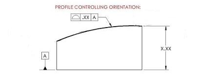
In the scheme proposed in CheckerHater's figure for "profile controlling orientation", does datum feature A and the existing dimensions (such as the non-basic height of the right upper corner) constrain translations of the true profile axis parallel to the XY plane (right-left-up-down on the drawing view)? If not, the tolerance zone is free to float in these directions, and from that, it should be clear why both the geometries of part 1 and part 2 in my sketch are acceptable.
 
How exactly tolerance zone translates up-down?

"For every expert there is an equal and opposite expert"
Arthur C. Clarke Profiles of the future

 
CheckerHater said:
How exactly tolerance zone translates up-down?

If you think it is limited by the +/- height dimension at the right side, it is only to some extent. The axis of the true profile arc can move in directions that have the up-down component even without affecting the location of the right upper corner relative to A. The tolerance zone is theoretical, not limited in length, and can be two coaxial arcs up to 180° (cylinders). If you consider the +/- located corner as a fixed "point" (in 2D thinking) at some distance above A - for example the nominal value of that height dimension, the entire arc can still be moved around in directions parallel to the "drawing sheet plane" so to speak, as long as that fixed point is kept on the periphery of the true profile arc. Different locations of the arc axis relative to the side faces and to datum A can produce the geometries of "part 1" and "part 2". The basic angle relative to A is kept constant the entire time - as you can see in the sketch in both versions.

If it's counterintuitive for you, try it yourself on your CAD program.
 
Are you referring to the compound angle idea that I mentioned? Specifically, another aspect of orientation in and out of the view?
I'm not discounting your point, but simply trying to find alternative words that might help. What threw me off was your continual use of "translation," which seems to be outside the realm of "orientation," which is the point being discussed.
 
Belanger said:
Are you referring to the compound angle idea that I mentioned

No, datum feature A locks 2 rotational degrees of freedom that will prevent the creation of the compound angle that you are referring to.

Belanger said:
What threw me off was your continual use of "translation," which seems to be outside the realm of "orientation," which is the point being discussed.

Datum feature references for a profile control do lock translational degrees of freedom, and when these degrees of freedom remain unlocked they affect the possible results for an arc-shaped feature like the one discussed - just like I showed (part 1 and part 2 obtained by movement of the axis in available degrees of freedom).
This however would be different if the feature was planar, then I agree that the basic angle alone would make it a pure orientation control, with the profile specification. The translation of the true profile would not matter. With the arc-shaped feature, it doesn't work the same way. The proof is in front of you in my sketch.
 
The compound angle is measured as the rotation perpendicular to datum feature A. It's called compound when more than one angle is used to depict it in orthogonal views. This is of some slight concern, but is not the subject of the example and could be solved in enough other ways that spelling them all out would be a distraction from the principle.

CH's example requires the basic angle to pass through a point that is X.XX from the bottom surface and on the right hand face, presumably +/- .tt. Your diagrams violate that requirement.

What you tried to show is that the true profile is free to shift (right to left in the diagram) relative to the end faces in a direction that is parallel to datum feature A. That is clearly unacceptable in that parts made that way would be rejected. Like the compound angle problem, this shift could also be restricted in multiple other ways that preserved using a directly toleranced dimension vertically locate the range to which the true profile would be restricted.
 
3DDave said:
CH's example requires the basic angle to pass through a point that is X.XX from the bottom surface and on the right hand face, presumably +/- .tt. Your diagrams violate that requirement.

My diagrams do not violate this requirement. Look again at the bottom image that shows the parts overlayed on each other. The height of the upper right corner is identical and may be equal to the nominal value of CH's "X.XX".

3DDave said:
That is clearly unacceptable in that parts made that way would be rejected.

It is only "clearly" unacceptable if the drawing defines so.

3DDave said:
this shift could also be restricted in multiple other ways that preserved using a directly toleranced dimension vertically locate the range to which the true profile would be restricted

And also preserve A being the only datum reference?
 
You kept the value but did not force the angle dimension to pass through the intersection, so the part would be unacceptable.
 
Belanger, CH, 3DDave,
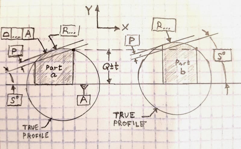
I made another sketch. Hopefully, it will help to explain the idea better than my previous one.

Sorry if I will sound like a broken record now, but first it needs to be acknowledged that only the datum reference frame constrains a true profile, which must be basically related to it, for profile tolerance definition. Physical part edges, corners, or plus-minus toleranced dimensions that are specified to locate these features - theoretically can be ignored when establishing a true profile. That is especially true if they are not referenced as datum features and do not have any interface with the datum feature simulators related to the profile specification. This is very "basic" (pun intended) and I truly hope this is something we all can agree on.

In the image below, datum feature A is the only datum reference and it constrains 3 degrees of freedom. Among the degrees of freedom that remain unconstrained are X and Y translations. The tolerance zone is disposed about the true profile, simulated by a full cylinder the diameter of which is two times the basic radius specified.

"Part a" is a part the designer is happy with because it turned out to be exactly as modeled. When "Part b" was inspected, the true profile and the tolerance zone that is fixed coaxially to it utilized the available freedom to translate parallel to the XY plane, unconstrained by datum feature A. Therefore part b also was accepted, even though it definitely didn't come out as the designer intended. The Q+/-t height dimension was produced as accurately as in the other part, but the "orientation" of the arc is completely different than what was intended. That is because, without additional constraints, the basic angle can't do its job. The degrees of freedom that remain free make the basic angle toothless. Note that I use the apostrophes for "orientation" because everything that happens here is very different from how orientation controls work for plane surfaces or axes and planes.

20200626_162325_htyx0i.jpg
 
Now I see the issue -- it doesn't have to do with any orientation around the x axis.
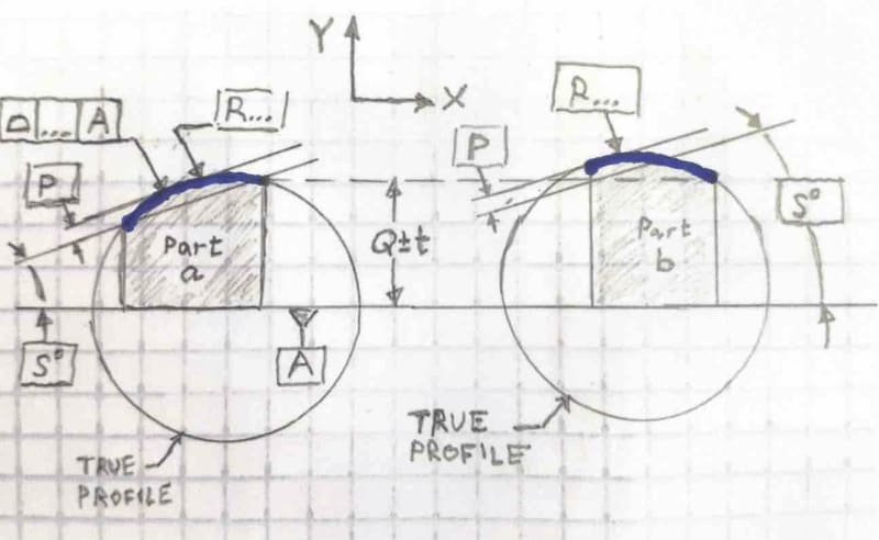
Your latest sketch illustrates the issue: According to the standard, the profile callout doesn't control the true profile. In other words, it doesn't require just any portion of an imaginary circle (radius) to fall in the tolerance zone. It requires the actual surface, as sampled within the boundaries of the two top corners, to fall within the tolerance zone.

Here, the dark blue shows what is required to fall within the zone. Clearly the picture on the right will not pass inspection:


RevisedSketch_o2pjxc.jpg


The relevant statement from ASME Y14.5-2018 is paragraph 1.4(o), which states: "UOS, all tolerances...apply for full depth, length, and width of the feature."
 
Belanger,
The blue portions you emphasized do fall within the tolerance zone in both cases. I didn't show in in the sketch but the tolerance zone is fixed to the true profile. The true profile defines the tolerance zone:

From ASME Y14.5-2009:
"8.3.1 Uniform Tolerance Zone
A uniform tolerance zone is the distance between two boundaries equally or unequally disposed about the true profile or entirely disposed on one side of the true
profile."


Any portion of the tolerance zone (in the example - two coaxial cylinders disposed about the true profile) can be used for the profile evaluation. The two parts are approved by being best fitted into different portions of the tolerance zone (which you showed in blue). I assume you know that the length of the tolerance zone is not limited by the length of the feature. For the tolerances to apply "for full depth, length, and width of the feature" the tolerance zone being established should extend beyond any limits set by the dimensions of the part.

When best-fitting for profile inspection, the tolerance zone (and the true profile) can shift relative to the DRF together with the considered feature, in the degrees of freedom that are not constrained by the datum references in conjunction with basic dimensions that define the true profile relative to those datum features. and as you can see there are no basic dimensions connecting between the true profile and datum A apart from the basic angle that doesn't prevent the shown shift.
 
Hi All,

I would like to refer back to something that Dean said earlier in the thread:

"The presence or absence of a basic dimension cannot affect what a profile tolerance controls."

I completely agree with this, and I find that looking at things this way really helps me to understand what is going on. Here is a modified version of CH's Profile Controlling Orientation drawing, with the basics removed:

ProfileOrientationNoBasics_shapkz.png


This should have exactly the same meaning as the original drawing. Nothing to do with the basic dimension, basic radius, or basic angle should matter. We have a true profile and a datum feature, from which we can generate a tolerance zone and a datum feature simulator.

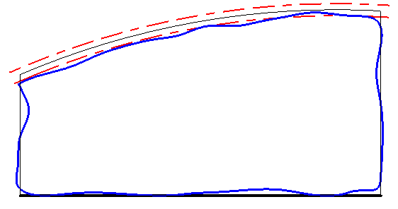
If the X.XX dimension was basic, the zone would remain centered around the true profile and the following as-produced part would fail:

StaticZone_j4roh5.png


The X.XX dimension isn't basic, so we look at Y14.5's examples and see that the directly toleranced height makes the datum feature reference "only constrain rotational degrees of freedom for the profile tolerance". This isn't very rigorous, but presumably it allows the profile zone to translate in the direction of that dimension (up and down) and thus allow the profile tolerance to pass:

StaticZone2_pgkfyc.png


There is still the issue of how to measure the X.XX height to verify that it is within its tolerance.

Evan Janeshewski

Axymetrix Quality Engineering Inc.
 
Evan and Burunduk... putting your two comments together, is that how we arrived at Burunduk's first picture (on June 25)?
I certainly agree that "the length of the tolerance zone is not limited by the length of the feature." My issue was regarding what portions of the full imaginary circle must lie within the tolerance zone. It looks like the answer is that it's undefined, because there were no other dimensions given that would define where to chop that imaginary circle. And any dimensions given about where to chop would need to tie into the same DRF as the profile, which gets back to the more fully defined profile examples that we all know and love.

So to go back to CH's picture (24 Jun 20 18:38) titled "profile controlling orientation" -- shall we conclude that datum A is meaningless there (unless the true profile were tied to it with basic dims, etc.)?
 
In Model Based Definition (MBD) that profile callout on CH's illustration would be "consumed" as location control regardless if the vertical dimension was basic or +/-. To make it something else than location control, the feature control frame would have to be modified, not the dimension type.
 
Belanger said:
there were no other dimensions given that would define where to chop that imaginary circle. And any dimensions given about where to chop would need to tie into the same DRF as the profile, which gets back to the more fully defined profile examples that we all know and love.

It is never about chopping the tolerance zone. The tolerance zone shouldn't be chopped. For an arc-shaped feature, the tolerance zone can be two full 360° coaxial cylinders. If it was a planar feature the tolerance zone could be infinite.

What is needed is additional constraints that will make the tolerance zone control what you want it too. What CH's "orientation profile" attempts to do is to set a specific ratio between the heights of the right side face (where it's controlled by the toleranced dimension) and the left side face. To achieve that by the profile control, these two side faces or one of them should definitely be involved in the datum reference frame. This can be achieved even without giving up on a toleranced dimension to control the height. I proposed a solution but it was ignored. Apparently solving it was of less interest than insisting that the original scheme can work.
 
J-P,

I wouldn't say that datum A is meaningless there. I would prefer to say that it has the same meaning as it normally would, and that the profile zone is affected by the directly toleranced dimension in some way.

Regarding the extent of the tolerance zone, let's not talk about that ;^). We know that tolerance zones must extend past the as-modeled length of the feature, but can we extend an arc-shaped zone into a full circle? I agree that this is undefined.

pmarc,

I would say that the dimension type makes a difference. I wish that Y14.5 didn't do it this way, but the presence of a directly toleranced dimension changes the meaning of the profile tolerance. This is still shown in Y14.5-2018 in Figure 11-32, and they even include the model-based view. If we ignore the fact that it's profile of a line and imagine that it's profile of a surface instead, then it's similar to the second example from the Henzold figure.

Keep in mind that I am saying that the dimension type makes a difference, and I'm not saying that I think that mixing directly toleranced dimensions with profile tolerancing is a good idea.

Evan Janeshewski

Axymetrix Quality Engineering Inc.
 
Burunduk,

A problem with many things shown in this thread, including the solution you proposed, is allowing a directly toleranced dimension to affect how a profile tolerance works. That should not be done because the directly toleranced dimension is ambiguous when used in that way. The direction of measurement for that dimension is undefined. There is no tolerance zone defined by that dimension. Combining something that is not rigorously defined with profile tolerance should not be done.

Dean
 
axym said:
the profile zone is affected by the directly toleranced dimension in some way.
Are you sure? I would say that only dimensions related to a DRF (i.e., basic dims) would tie that profile tolerance to datum A.
If we accept the notion that profile doesn't control orientation in that instance (going by the previous dozen or so posts), and it doesn't control location (because now we're talking about directly toleranced dims), then doesn't it follow that datum A is meaningless there?

axym said:
I would prefer to say that it has the same meaning as it normally would
What is that normal meaning, if we have now discounted orientation, and the location is to be tackled with directly toleranced dims?

I'm just trying to push all of these ideas to their furthest corners... this is a great discussion!
 
Burunduk,

OK I think I see what you're getting at - I didn't understand it before. The Part 2 contour in your figure from June 25 at 10:22 was created by extrapolating the arc-shaped tolerance zone boundaries and extending datum feature simulator A. Like this:

ExtendedZone_mv7p88.png


Is this the kind of effect you''re thinking of?

It seems ridiculous at first glance, but I'm not sure if there is anything in the standard that disallows it. This could occur even if the height dimension was basic.


Evan Janeshewski

Axymetrix Quality Engineering Inc.
 
J-P,

I haven't accepted the notion that profile doesn't control orientation in this instance. I didn't really follow the logic of those dozen or so posts, or how you were able to reach the conclusion that orientation is somehow not controlled. I'll have to go back and see if I can make sense of it. It seems that we have several different effects happening in the same example.

Evan Janeshewski

Axymetrix Quality Engineering Inc.
 
Status
Not open for further replies.

Part and Inventory Search

Sponsor