Continue to Site

Eng-Tips is the largest engineering community on the Internet

Intelligent Work Forums for Engineering Professionals

  • Congratulations KootK on being selected by the Eng-Tips community for having the most helpful posts in the forums last week. Way to Go!

Sway or nonsway RC columns for my space frame

Status
Not open for further replies.

hamza41

Civil/Environmental
Jul 7, 2015
51
Hello,

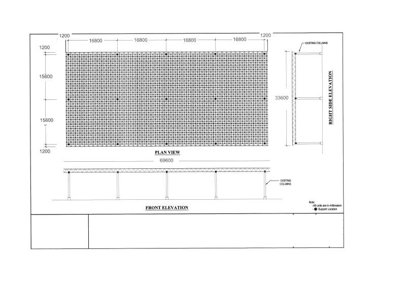
I'd like to check the stability of RC columns against the reactions of a space frame. The columns' height is 12 m and their diameter is 60 cm. The issue is to decide the effective length factor value to adopt for this case to determine the critical buckling load P[sub]c[/sub].
At first sight, the structure is sway as no bracing elements are present.
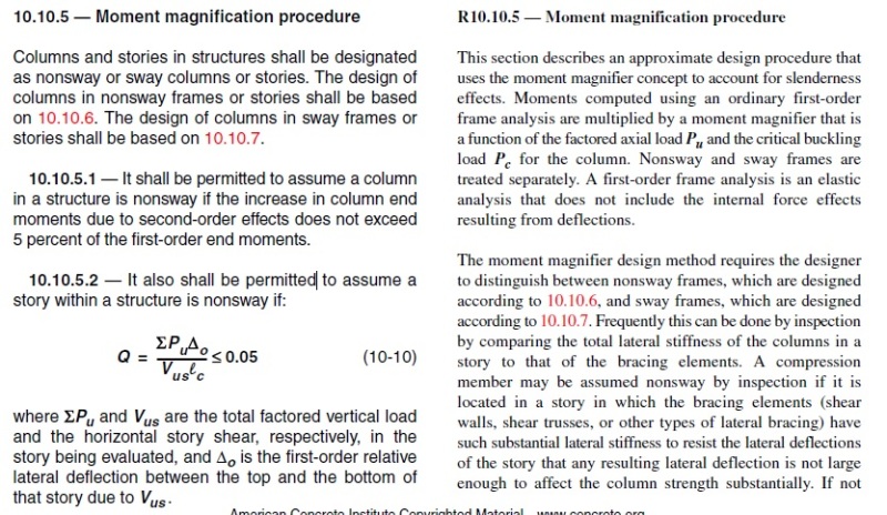
The question is: can I consider my structure as nonsway if it complies with the following condition (10-10) of ACI 318-11 and adopt an effective length factor of 1 instead of 2, or is this conditon only available for the determination of the Moment magnification procedure ?

Thank you.
SF_xqo8gw.jpg

ACI_erqevh.jpg
 
Replies continue below

Recommended for you

I think this is intended only for Moment magnification. For example, a column may be classified as slender or not depending on the K value of its deflected shape. This shape will be defined by column's end restraint conditions and the sway or nonsway behaviour of the frame. If you you change the column K value by (10-10) prescription and the column cross the klu/r<22 limit you'll need no magnified moments, but actually you do get some extra moments by real column behaviour.

The difference in state a magnification by sway or nonsway remains in the consideration of P-Delta Effects, besides the P-deflection ones.

 
I agree with Ytus, as a cantilever column, K=2.0 for the effective length factor. In addition to that P-Delta effects, and perhaps foundation flexibility, ought to be considered. If your columns are non-slender, that will definitely help out with P-Delta.

I like to debate structural engineering theory -- a lot. If I challenge you on something, know that I'm doing so because I respect your opinion enough to either change it or adopt it.
 
If this structure is the same as the existing one you post in early May, [thread507-424485] proceed carefully!
 
They are cantilevered columns, or really cantilevered beams oriented vertically.
 
Thank you all.
Yes Ingenuity, it's the same structure. The concrete tests reveals high level of chloride content, it seems to be the principal cause of steel corrosion that has led to concrete cracking.
The columns are always slender even with a k factor of 1 and I will need a magnification factor in all cases. By considering a factor equal to 2 the design load exceed the critical buckling load. I thought the columns stiffness would provide lateral resistance, in view of the non significance of lateral loads.
 
Determining the structure as frame type (sway or nonsway frame) is the first step. The effective length factor k should be determined by the frame type and the ratio of the sum EI/L for beams to the sum EI/L for columns per the Jackson and Moreland Alignment Charts. The k should be 2 in your case.
 
Read the commentary beside it. If there are bracing elements supplying a large portion of the resistance to horizontal loading, then it is a braced frame. Otherwise it is a sway frame.

You have stated that there are no bracing elements, so it is a sway frame.

And stop trying to use "interpretations" of unrelated code clauses to get around engineering logic.
 
hamza41 said:
...the design load exceed the critical buckling load.

Double check your calculation of the critical buckling load, P[sub]c[/sub]:

For a kl[sub]u[/sub] of 24,000 mm, and assuming EI=0.4E[sub]c[/sub]I[sub]g[/sub] (≅70 x 10[sup]12[/sup] N.mm[sup]2[/sup]), I calc P[sub]c[/sub] = 1,200 kN​

What is the magnitude of your factored axial load on the interior columns?
 
Hi Ingenuity,
As per ACI 318-11 Eq. (10-15) EI = 0.4E[sub]c[/sub]I[sub]g[/sub] / 1 + β[sub]dns[/sub] ≅ 30 x 10[sup]12[/sup] N.mm²
l[sub]u[/sub] = 12.5 m taken from the top of foundation
P[sub]c[/sub] = 480 KN and my factored axial load is around 800 KN
 
A thought: all of the columns will be constrained to buckle together so it may be overly conservative to base the design on the heavily loaded central bay (if that's what you've done). Granted, it sounds as though you've got a significant deficiency to make up.

I like to debate structural engineering theory -- a lot. If I challenge you on something, know that I'm doing so because I respect your opinion enough to either change it or adopt it.
 
You're right Ingenuity, βds shall be substituted for βdns and can be equal to zero for sway columns, as per ACI 318-11 R10.10.7.4 :

"In the calculation of EI, βds will normally be zero for a sway frame because the lateral loads are generally of short
duration. Sway deflections due to short-term loads such as wind or earthquake are a function of the short-term stiffness
of the columns following a period of sustained gravity load. For this case, the definition of βds in 10.10.4.2 gives βds = 0.
In the unusual case of a sway frame where the lateral loads are sustained, βds will not be zero. This might occur if a
building on a sloping site is subjected to earth pressure on one side but not on the other."


In this case, is the thermal load to be considered ? especially with high temperature differences and long structure.
 
KootK said:
A thought: all of the columns will be constrained to buckle together so it may be overly conservative to base the design on the heavily loaded central bay (if that's what you've done).
Can you please develop you idea ?
May be the space frame is not enough stiff to constrain the columns to buckle together.
Do you mean that I don't have to check each column's loads against its critical load ?
 
hamza41 said:
Can you please develop you idea ?

Based on your comment about the stiffness of the space frame, it sounds as though you've got the idea. I wholly expect that the columns will buckle as a system, with more lightly loaded columns bracing heavier loaded columns for a time, rather than as individual columns somehow plowing through the space frame independently. Some strength and stiffness would be required of the space frame but I don't see that being much of a problem.

As a high level check, I would sum the axial capacities of all the columns and compare that to the total axial load on all of the columns. If that gets you into the right ballpark, dig a bit deeper.

I like to debate structural engineering theory -- a lot. If I challenge you on something, know that I'm doing so because I respect your opinion enough to either change it or adopt it.
 
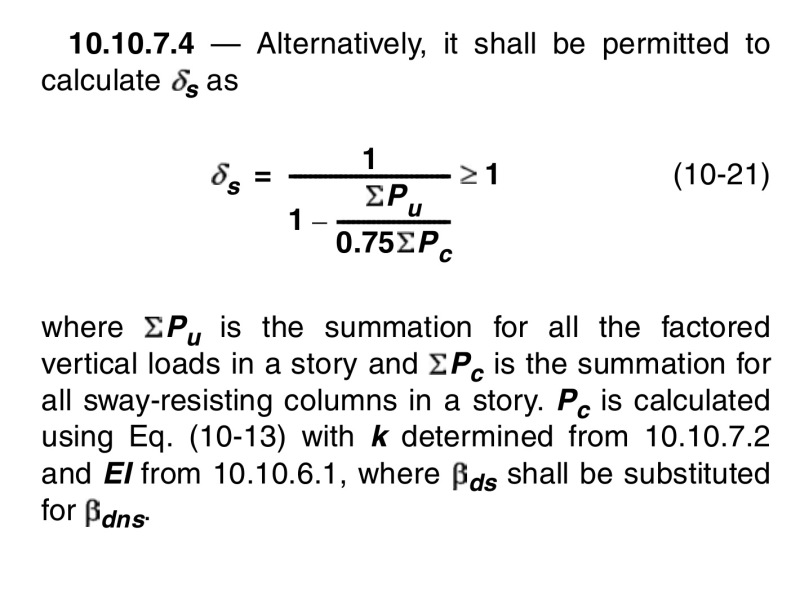
Check out §10.10.7.4 and equation (10-21) where the sway moment magnifier uses the summation of the axial to buckling loads across the entire 'story':

image_smobqd.jpg


Hopefully your δ[sub]s[/sub] does not magnify too much!
 
I think your columns are strong enough, based on your agreement with Ingenuity. But I wouldn't use KootK's analogy. Too much like two drunk sailors leaning against each other...stable for a while.

Now you have to design the footings to support the cantilever columns. If the footings can rotate, all bets are off.
 
hokie66 said:
But I wouldn't use KootK's analogy. Too much like two drunk sailors leaning against each other...stable for a while.

Is this, conceptually, much different than the ubiquitous practice of having "gravity columns" that are stabilized laterally by other elements? It takes a village. As evidenced by Ingenuity's latest, the notion of whole level buckling is kinda baked into the ACI cake. And one of the reasons that AISC's modern Direct Design Method was developed was to specifically give account to system behavior of this sort.

I like to debate structural engineering theory -- a lot. If I challenge you on something, know that I'm doing so because I respect your opinion enough to either change it or adopt it.
 
Australian and many other code logic is that the stiffer columns will partly brace the less stiff columns. But they are still basically sway columns.

The only way to determine the relative buckling effects in this sort of situation is to do a full 2nd order sway analysis. The simplified slenderness rules in codes do not apply in this case. They basically consider the "average" column and do not allow the designer to evaluate the effects on the worst column.
 
hamza41 said:
and my factored axial load is around 800 kN

Assuming 800 kN is for your INTERIOR column factored load, and then assuming that the EDGE column factored loads are 400 kN (50% trib area) and CORNER column factored loads are 200 kN (25% trib area) then:

ΣP[sub]u[/sub] = 3 x 800 + 12 x 400 + 4 x 200 = 6,500 kN​

Further assuming all 15 columns have the same rebar size and concrete strength:

0.75ΣP[sub]c[/sub] = 0.75[15 x 1200] = 13,500 kN​

So 'plug and chug' into equation (10-21):
Capture_m1i8pz.png

So basically doubling your sway moments.

At 1,200 kN factored axial load your corresponding moment capacity is about 500 kN.m (assuming you have 35 MPa concrete and 1.5% reinforcement).
 
Thank you all,
The space frame supplier provided reactions on supposed rigid supports. When I designed the structure on supports of equivalent columns' stiffness, the horizontal reactions have been reduced to some negligebale values (max Fx = 0.6 KN). It should be closer to the reality than rigid support.
 
Status
Not open for further replies.

Part and Inventory Search

Sponsor