Continue to Site

Eng-Tips is the largest engineering community on the Internet

Intelligent Work Forums for Engineering Professionals

  • Congratulations KootK on being selected by the Eng-Tips community for having the most helpful posts in the forums last week. Way to Go!

Tapered wedge as a datum feature

Status
Not open for further replies.

gabimo

Mechanical
May 2, 2013
124
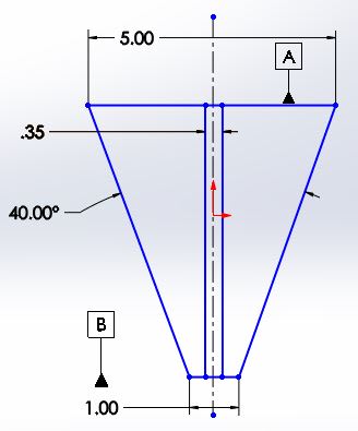
If a tapered wedge IS defined with ± angle and direct toleranced dimension on one end, can its middle plane be used as a datum feature?
How to generate the centerplane / middle plane as a datum from the non-parallel but planar adjacent surfaces?

Details: A part has its left and right sides tapered and has its primary datum the feature that connect these two sides.
Secondary datum is intended to be the middle / center plane of the tapered sides.
There are three holes on the part (normal/perpendicular to the primary) that should be centered (within some tolerance) to the secondary (middle plane).
Is the middle plane created by this tapered side walls a valid datum?
 
Replies continue below

Recommended for you

To answer the question of "CAN it be used as a datum feature?" I'm pretty sure you can, but I'm not positive. The problem I see with this configuration is that using a +/- tolerance on the angle changes where the origin of measurement is from part to part. Your origin of measurement will HAVE to be from the intersection of the two sides, unless you customize the datum reference frame. I would seriously reconsider this approach in favor of a basic angle with a profile of a surface tolerance.

John Acosta, GDTP Senior Level
Manufacturing Engineering Tech
 
John,
By "Your origin of measurement will HAVE to be from the intersection of the two sides" another way to think about it would be that your datum feature simulators would have to always make full contact with the angled faces instead of fixed at a nominal angle, right?

gabimoang,
As far as how to reference it - could you call out each side as a datum then reference them as a composite datum feature? Ie: one side is datum feature , the other as [C] then referenced together as [B-C] ?
 
chez311 said:
By "Your origin of measurement will HAVE to be from the intersection of the two sides" another way to think about it would be that your datum feature simulators would have to always make full contact with the angled faces instead of fixed at a nominal angle, right?

Yes, that's what I'm saying.

John Acosta, GDTP Senior Level
Manufacturing Engineering Tech
 
DA_qu2jkp.jpg
 
How do you plan to simulate datum feature B?

John Acosta, GDTP Senior Level
Manufacturing Engineering Tech
 
John,
I do not know. That's exactly my question too.

How to simulate the centerplane of two tapered planar features?
 
Hi,gabimoang:

I agree with Chez311. I would label the side as datum feature A, and the right side as datum feature B. Top face will be datum feature C. 40 degree angle will be a BASIC dimension. You need to throw in a profile tolerance. You can then use A-B and C in your feature control frame.

Best regards,

Alex
 
jassco,

I agree a basic angle/width with profile is probably the best solution. Just to note your suggested datum C top surface as a secondary datum would constrain no additional DOF over [A-B] and would be redundant. It would need to be called out as primary to be involved at all in constraining DOF.
 
Hi, chez311:

Good point! It is better to use datum C as secondary datum feature based on OP's design intents. In this case, a translation degree of freedom in vertical direction needs be removed from primary datum features. This will lead to a custom datum reference.

Best regards,

Alex
 
jassco,

gabimoang said:
Details: A part has its left and right sides tapered and has its primary datum the feature that connect these two sides.
Secondary datum is intended to be the middle / center plane of the tapered sides.

Note the problem definition in the OP and gabimoang stated the tapered portion should be a secondary datum. Though the datum structure may be a bit strange, there should really be no need for a custom DRF unless OP deems it necessary to allow the tapered portion to control any of the translational/rotational DOF that the top surface already controls. Custom DRF really tends to be an academic discussion with little basis in real, functional parts - this can of worms has been opened several times recently and my opinion, as well as the general consensus, is to avoid it if at all possible.


Note - sorry about the deleted post. I got a bit confused and realized I went off in the wrong direction.
 
Hi, chez311 and gabimoang:

I think there are a couple of reasons why top face needs to be secondary datum feature.

Firstly, we normally choose larger surfaces as primary datum features. In this case, left and right side faces are larger than top face.

Secondly, if you choose top face as datum feature A, then it will be difficult to determine "the middle plane" between the two side faces. As a secondary datum, this "middle plane" (A-B) needs to be perpendicular to datum feature A. I am not sure if current CMM software have ability to determine a "middle plane" between two planes while maintaining this perpendicularity to datum feature A. In math, this is called "conditional best fit".

Best regards,

Alex
 
jassco said:
Firstly, we normally choose larger surfaces as primary datum features. In this case, left and right side faces are larger than top face.

Err....what? I mean you want your primary datum to allow stable, repeatable measurement but size does not drive datum selection/precedence in this manner.

jassco said:
Secondly, if you choose top face as datum feature A, then it will be difficult to determine "the middle plane" between the two side faces. As a secondary datum, this "middle plane" (A-B) needs to be perpendicular to datum feature A.

This would be driven by the functional requirements, not by any need to exactly determine a middle plane. I'm not convinced there would be any issue with determining your mutually perpendicular planes that make up the DRF with the tapered feature as secondary. If someone said they needed the tapered feature primary/top surface secondary with a custom DRF to allow the otherwise redundant secondary top surface to constrain DOF I would say they would be required to prove with sufficient evidence why this is necessary for proper part function/fit - CMM measurement is NOT a good enough reason.
 
chez311 said:
could you call out each side as a datum then reference them as a composite datum feature? Ie: one side is datum feature , the other as [C] then referenced together as [B-C]


If this solution is used, what is establishing the location relationship between B and C?

Also another related question: are you going to use angularity or perpendicularity to orient primary datum feature A to the secondary B-C compound?

Left face: perpendicularity or angularity to A primary and B-C secondary? = which becomes datum feature B
Right face: perpendicularity or angularity to A primary and B-C secondary? = which becomes datum feature C


greenimi,

As I see it there are several options, listed in no particular order. Datum A is the top face, datum B and C are the left and right faces. I know the OP referenced directly toleranced (+/-) dimensions but I am including solutions with profile/basic dimensions because I think those are the best options.

1) all basic angles/dimensions. 2x profile tolerance applied to B and C separately in reference to A. referenced as [B-C] (similar to fig 4-22 but the datum features are at an angle to each other instead of parallel)
2) #1 but with multiple single segment or composite to allow refinement of orientation vs. location (upper FCF/PLTZF would probably be slightly looser than #1)
3) #1 adding 2x angularity controls to refine orientation (profile FCF would probably be slightly looser than #1)
*4) basic angles and directly toleranced width/location. 2x angularity controls applied to B and C separately in reference to A. referenced as [B-C]. (similar to fig 6-2 but the features are at an angle to each other as well as the referenced datum instead of parallel)
**5) all directly toleranced angles/dimensions. Either no controls (not recommended) or 2x flatness controls applied to B and C separately. referenced at [B-C].

*I hope this isn't improper, I think as long as the angular dimensions are basic, standard orientation controls can be used? Someone can correct me if not.
**This is the only way I can think of to do it with all directly toleranced dimensions (per OP's original statement) - I am not sure if this is allowed, but I can't think of a reason why it wouldn't be.

greenimi said:
Also another related question: are you going to use angularity or perpendicularity to orient primary datum feature A to the secondary B-C compound?

Left face: perpendicularity or angularity to A primary and B-C secondary? = which becomes datum feature B
Right face: perpendicularity or angularity to A primary and B-C secondary? = which becomes datum feature C

I'm not quite clear on what you mean here, I think I answered it above but it sounds almost like you are suggesting self-referencing datums. I would want to try and avoid that.
 
chez311 said:
1) all basic angles/dimensions. 2x profile tolerance applied to B and C separately in reference to A. referenced as [B-C] (similar to fig 4-22 but the datum features are at an angle to each other instead of parallel)

If option #1 is used, then what would the the difference and which option would be the correct (read standardized) callout for datum features B and C: would you use profile (as indicated in your statement) or would you use perpendicularity/ angularity?

I am asking from point of view of the relationship between primary and secondary: is it orientation or is it location? Looks like it is location, but I might be mistaken.

chez311 said:
it above but it sounds almost like you are suggesting self-referencing datums
I don't think I am suggesting self-referencing datums if I say:

datum feature B: profile (or perpendicularity/ angularity) to A primary and B-C secondary
datum feature C: profile (or perpendicularity/ angularity) to A primary and B-C secondary
Why do you think it is self-referencing?

* edit for adding A primary and B-C secondary, which have been missed on my first attempt.


greenimi,

As far as correct/standardized I don't have that answer - perhaps someone else more experienced than I could step in and say. I *think* all the solutions I presented are valid, but I could well be wrong. Edit - I see what you're saying, sorry - I would go with either of the #1, #2, or #3 utilizing profile (or a mix of profile/orientation controls) with basic dimensions only. My opinion is that those would be most the most proper and best way.

I also have a suspicion that my #2 with composite and #3 with angularity/orientation refinement accomplish the same thing as long as A is referenced (datumless composite would be different). #2 with multiple single segment is close, but I think different because it fixes location to A.

greenimi said:
I am asking from point of view of the relationship between primary and secondary: is it orientation or is it location? Looks like it is location, but I might be mistaken.

I think the relationship is both orientation and location - isn't that what you would want? I don't think it would be acceptable to control the taper with orientation only, if you don't control its location you could technically accept a taper infinitely large or small (as it floats away or towards datum A) as long as it is oriented correctly.

greenimi said:
datum feature B: profile (or perpendicularity/ angularity) to A primary and B-C secondary
datum feature C: profile (or perpendicularity/ angularity) to A primary and B-C secondary
Why do you think it is self-referencing?

I'm a little confused, if you define B with B-C or C with B-C (regardless of primary/secondary) how is that not self referencing? You are controlling the datum feature with a DRF that includes the datum feature being controlled...
 
chez311 said:
I'm a little confused, if you define B with B-C or C with B-C (regardless of primary/secondary) how is that not self referencing? You are controlling the datum feature with a DRF that includes the datum feature being controlled...

chez311,

I am thinking that is not self-referencing because is the same concept as discussed in this thread

Why you did not have any issues with the picture I have posted from 14 September:
Cylindrical surface datum feature C, located within Ø0.01(MMC) to C-D
Cylindrical surface datum feature D, located within Ø0.01(MMC) to C-D

and you have a problem with self-referencing in this thread/discussion
(datum feature B: profile (or perpendicularity/ angularity) to A primary and B-C secondary
datum feature C: profile (or perpendicularity/ angularity) to A primary and B-C secondary ) ?

Trying to understand your thinking. I am not saying that you don’t see something I am not able to see.

For me looks like an equivalent concept, but not applied to a cylindrical surface (as it is in pmarcs’s conversation) but to a planar one (as applied to OP’s discussion)
Probably is too early in the day, but again, I do not see why it is self-referencing in kedu’s gabimoang's case.

By the way, question for you (and I do not mean to hijack the thread, but just for clarification): if I have a runout on a cylindrical surface (call it datum feature A) within 0.01 to A, would you say that is self-referencing or not? Please let me know your thoughts.
 
greenimi,

My apologies, your question is a complex one and I wanted to make sure I gave it the attention it deserves.

Your inquiry is a valid one, however I think the key difference is the utilization of profile vs runout with self-referencing datums.

Your example of runout with a compound datum (pulled from fig 9-4) I believe is also self-referencing. The only reason why I didn't draw issue with it is runout with self referencing datums is a well established practice and has several examples supporting its use in the standard (9-4, 9-6, 9-7 all have self referencing datums). If you read through some correspondences on the topic ( there seems to be some division on whether it is really proper or "stands up to scrutiny". It makes me wonder if there wouldn't be a better way of specifying such a requirement - though I'm not sure if it is possible with the available tools in Y14.5, the one thing that comes to mind is possibly the new "dynamic profile" modifier that will be coming in the new 2019 standard.

greenimi said:
if I have a runout on a cylindrical surface (call it datum feature A) within 0.01 to A, would you say that is self-referencing or not?

I think with a single feature referencing only itself with runout (not a compound datum like your previous example similar to 9-4) is also self referencing but is confusing at best, and I think in most cases ends up being a form control only. Referencing thread it seems that it is agreed that typically for total runout it would be equivalent to cylindricity. Circular runout vs. circularity for a single, self-referencing datum seems to be a more complex question.

Reading through that thread it seems that I may differ from some in my definition of "self-referencing", I would consider ANY feature which is controlled with a DRF which includes that feature to be self-referencing - not just ones that result in an invalid combination (ie: position of A relative to A). Maybe more precise terminology is needed to differentiate the two?

greenimi said:
For me looks like an equivalent concept, but not applied to a cylindrical surface (as it is in pmarcs’s conversation) but to a planar one (as applied to OP’s discussion)

The reason I draw issue with the concept (actually I said to avoid it, not that its invalid) as applied to a profile tolerance on a planar feature is that there is no real documentation in the standard on it. From what I can tell, there is somewhat of a consensus that self-referencing datums with profile tolerance results in a "halving" of the available tolerance zone - however this is not a well known topic and in actual practice (inspection and gauging) approaches/interpretations may differ.

Some threads which discuss the topic of self-referencing datums combined with profile. I realize your example is slightly different (B and C controlled separately with B-C instead of both B and C controlled together with B-C) however I think the result is the same - if not even more difficult to interpret.
 
Status
Not open for further replies.

Part and Inventory Search

Sponsor