Continue to Site

Eng-Tips is the largest engineering community on the Internet

Intelligent Work Forums for Engineering Professionals

  • Congratulations SDETERS on being selected by the Eng-Tips community for having the most helpful posts in the forums last week. Way to Go!

tertiary datum to lock rotation help

Status
Not open for further replies.

R1chJC

Marine/Ocean
Apr 15, 2015
51
Hi All,

I have a part that looks like a figure of 8 with two holes, similar to a chain link.
The holes need aligning with one another but i'm struggling to decide how to apply a tertiary datum to lock any rotation - see attached.

I don't want the holes wandering off so the wall thickness get reduced.

See attached picture.

Any help would be great.
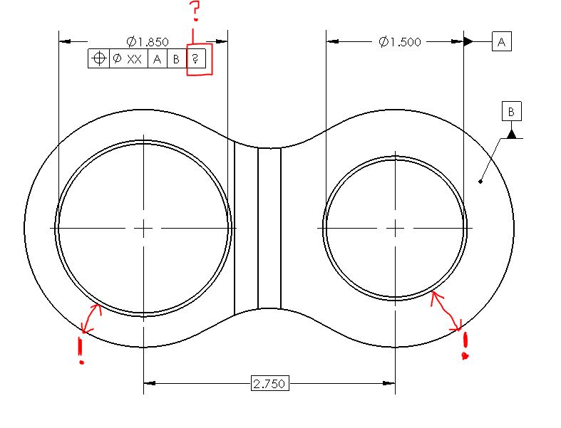
Part_vocpg2.jpg
 
Replies continue below

Recommended for you

R1chJC,

Are you drawing per ASME Y14.5-2009 ?

Why not just leave the position tolerance to |A|B| and hold the outside profile to a profile of a surface tolerance to |A|B| which holds it in simultaneous requirements?

Is the 1.500 dia hole actually more "important" than the 1.850 hole? If so, you could leave the position tolerance to |A|B| on the 1.850 dia hole, reference it as datum feature C, and hold the outside profile to |A|B|C|. Alternately if it is not more "important" you could hold both holes and the outside profile to |A| with simultaneous requirements, or even some combination of the two (both holes position to |A| and referenced as datum features B and C respectively then referenced together in the profile as either |A|B|C| or |A|B-C|).

Also note your datum feature B needs to be related back to |A| in orientation.
 
Apologies - I just realized the 1.500 dia hole is datum feature A and the planar face is B. I edited my post to reflect this.
 
And the natural question is:
What would be the difference between
- Ø1.850 holes to be positioned to |A|B| and become C and the outside profile to be located to |A|B|C
and
- Ø1.850 holes to be positioned to |A|B| and the outside profile to be located to |A|B| and let the simultaneous requirement take care of the rotation lock (as requested by the OP).

 
greenimi,

I don't think OP requested rotation be constrained by simultaneous requirements - only that it be constrained and I provided two solutions.

I would have to do a mock up but I believe with |A|B|C| will be more strict as the basic profile and related profile tolerance zone will have to be oriented to C first but with |A|B| and simultaneous requirements allows slightly more rotation between the measured profile and 1.850 dia hole as they would be satisfied together.
 
What would be the difference if everything was related to B alone (providing that outline dimensioned in basic)?

"For every expert there is an equal and opposite expert"
Arthur C. Clarke Profiles of the future

 
Chez311 said:
I would have to do a mock up but I believe with |A|B|C| will be more strict.................

That is my feeling (recollection from previous discussions) too.

 
CH,

Well in that case B would be primary, certainly different than |A|B|C| or |A|B| with simultaneous requirements. I initially figured similarly (as you can see by my edit) but once I realized OP had set the hole A as primary and B as secondary I figured they had a reason for doing so - due to assembly or function. If B can actually be primary then by all means that would be a viable option.
 
That's one of the reasons I was asking: must [A] really be primary?

"For every expert there is an equal and opposite expert"
Arthur C. Clarke Profiles of the future

 
Hi All,

Thanks for your inputs. Some good ideas thanks!

I don't have a preference at this point whether the constraints come from a simultaneous requirements or not.

Datum surface abuts a mating faces so I chose the corresponding hole as [A].

Part_2_kwtjgz.jpg
 
If it's a mating face, it better be primary datum.

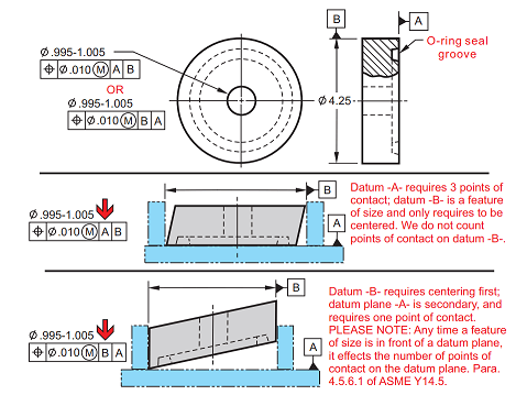
Your situation is known as "Datum Axis and Datum Plane Combined"
You have to carefully chose your datum order according to the way the part will function:

Datum_Axis_and_Datum_Plane_Combined_ypiyuc.png


"For every expert there is an equal and opposite expert"
Arthur C. Clarke Profiles of the future
 
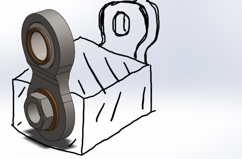
Agreed with CH. Judging by your rough sketch, I assume the hole is in fact a clearance hole for a stud - in that case I would choose the planar datum B as primary as in the assembly it will constrain 3 DOF.
 

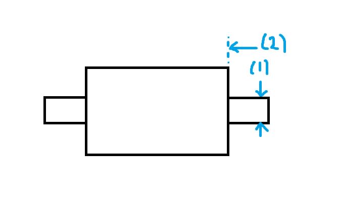
In this instance the part locates on the stud(1) and then slides down to abut onto the mating face (2).

I was trying to mirror that with the datum sequence.

Order_ol4kbx.jpg
 
What kind of fit is there to the stud when bolted up? Is there clearance under all conditions? If so B should be primary.
 
Yes, clearance in all conditions - but only a few thou.


I would say then that datum feature B as the abutting face should be primary. Order of assembly can be important, but insofar only as it contributes to how each feature constrains degrees of freedom.
 
I was thinking of a datum system like that shown in figure 4-47 in 2009 that specifies adjustable datums to "capture" the part. Maybe?

Certified Sr. GD&T Professional
 

I can see how the datum sequence effects points of contact in the diagram from CheckerHater.

I'm struggling to see how one might be preferred over the other in my application.
 
The datums features and their sequence are controlled by part functionality. Mfg and inspection concerns should be addressed, but in the end the part needs to work as intended.

Certified Sr. GD&T Professional
 
Status
Not open for further replies.

Part and Inventory Search

Sponsor