Continue to Site

Eng-Tips is the largest engineering community on the Internet

Intelligent Work Forums for Engineering Professionals

  • Congratulations SDETERS on being selected by the Eng-Tips community for having the most helpful posts in the forums last week. Way to Go!

tertiary datum to lock rotation help

Status
Not open for further replies.

R1chJC

Marine/Ocean
Apr 15, 2015
51
Hi All,

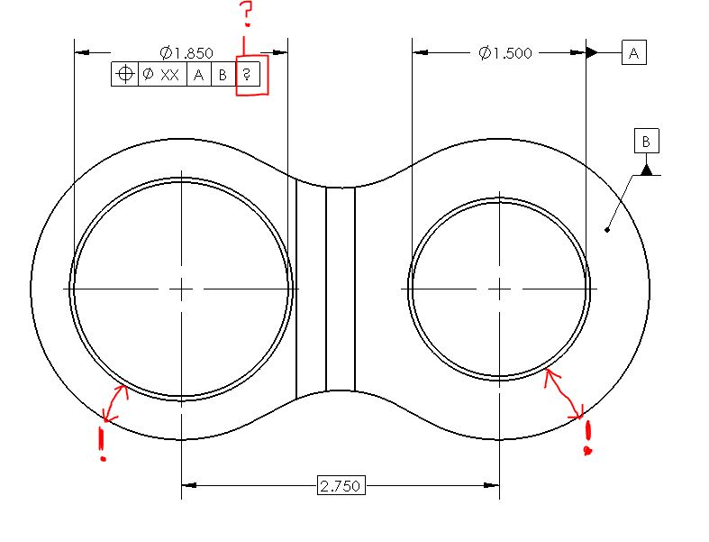
I have a part that looks like a figure of 8 with two holes, similar to a chain link.
The holes need aligning with one another but i'm struggling to decide how to apply a tertiary datum to lock any rotation - see attached.

I don't want the holes wandering off so the wall thickness get reduced.

See attached picture.

Any help would be great.
Part_vocpg2.jpg
 
Replies continue below

Recommended for you


pylfrm said:
Why not directly specify the minimum acceptable wall thickness?

Yep could do that, although I liked the idea of using a profile tolerance and simultaneous requirement to control rotation as suggested in an earlier post.

chez311 said:
What kind of fit is there to the stud when bolted up? Is there clearance under all conditions? If so B should be primary.
Presumably if there was interference then B should remain secondary? Is this because an interference fit on the stud would not allow the part to 'tilt' and obtain a 3 point contact against the mating part?
 
pylfrm said:
Why not directly specify the minimum acceptable wall thickness?

I do not like/agree that adding such a note/ value/dimension on a drawing is a robust product definition.
I even would say it is more like a pseudo-engineering. I know Y14.8 (casting standard) shows it in fig 3-24, but I still think the real world/engineers can do better than that.
The designers/engineers should be able to calculate the required tolerances/ tolerance zones and have an unambiguous definition with GD&T and the minimum acceptable wall thickness would be a driven (not a driving) feature or characteristics of the part.


@greenimi: why wall thickness cannot be driving feature if it is functionally critical?

@everybody: the rounded shapes on the part outline actually have opposing points, so they may qualify as FOS. Could we use position to control them?
Just position at MMC, as they are probably may be less accurate then precision bores.

"For every expert there is an equal and opposite expert"
Arthur C. Clarke Profiles of the future

 
R1chJC,

Essentially yes, though I find it more useful to think of it in terms of constraint of degrees of freedom. If we take (z) to be normal to the planar surface, then in the theoretical case you presented (press fit/interference between the stud and the bore as datum feature A) then datum feature A would constrain translation in (x,y) as well as rotation (u,v), and the planar datum feature B would constrain translation in (z). However, in your actual assembly (clearance between stud/bore) planar datum feature B would constrain translation (z) as well as rotation (u,v) and datum feature A would only constrain translation (x,y). The application/precedence of your datum feature references in your DRF should reflect this.

That being said, transition fits (clearance/interference between features depending on where they are produced inside their tolerance zone) as well as introduction of forces on flexible parts (ie: any real world part - nothing is truly rigid) can make it difficult to determine what features constrain each DOF. The only thing you can do at that point is to as closely determine which features contribute the most to the constraint of each DOF and possibly include a specification for restraint of the part during measurement to replicate the condition during assembly, if necessary.
 
CheckerHater said:
why wall thickness cannot be driving feature if it is functionally critical?

CH,
Because wall thickness is not a standardized term and people might has different interpretations on what that means. How many time did you see only on this forum when someone is asking for help to calculate the minimum wall thickness and we came up with at least two different answers and not due to the lack of knowledge but to a different interpretations on what that means.
There are multiple examples here on eng-tips.

Now, in the real world is even worse and I think that risk (of multiple interpretations) should not be taken at the design level.


R1chJC,

I too would likely prefer an approach using a profile tolerance as part of a simultaneous requirement, with B as the primary and possibly the only datum feature. A directly specified minimum would make most sense if wall thickness were the only concern, but I imagine that's not really the case.


greenimi,

Using the words "WALL THICKNESS" on the drawing would probably be a bad idea. Instead, imagine replacing the red markups labeled "!" in the original post with actual dimensions such as ".350 MIN" and ".480 MIN". What's not robust about that?


pylfrm
 
R1chJC said:
I'm struggling to see how one might be preferred over the other in my application.

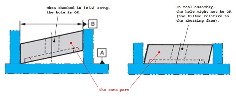
You could look at it from this perspective:

capture_bpualu.jpg


To avoid this kind of problems, the set up of the part for inspection (i.e. the order of datums specified in a feature control frame and their material boundary modifiers) should mimic real assembly conditions as close as possible.


R1chJC said:
Yes, clearance in all conditions - but only a few thou.

When estimating the amount of clearance, did you take potential perpendicularity error between the dia. 1.500 hole and the abutting face under consideration?

Based on your 3D sketch, it seems like addtional bushing is pressed into the dia. 1.500 hole. When estimating the amount of clearance, did you take under consideration the fact that the hole in the additional bushing may have extra coaxiality error relative to the hole in the part that is being discussed?
 
pylfrm said:
in the original post with actual dimensions such as ".350 MIN" and ".480 MIN". What's not robust about that?

If .350 MIN and .480 MIN. in the original post is robust, then would you agree that we can safely assume adding another dimension for MAX is also robust? Why wouldn't be?

Then if we have a MIN and MAX dimension what is the difference between using plus/minus dimensioning scheme?

Am I missing something? Or maybe you will say that I am using the "straw man" (EDIT: Hasty generalization) argument.


greenimi,

For an upper limit it might be debatable whether the envelope principle applies. For a lower limit there is no such concern.

MAX/MIN and plus/minus are just different ways of expressing a tolerance. There is no difference in meaning if the limits are the same.

Can you imagine more than one plausible meaning for the dimensions described in my previous post? I can't.


pylfrm
 
Status
Not open for further replies.

Part and Inventory Search

Sponsor