Italo01
Structural
- Sep 4, 2021
- 169
Hello,
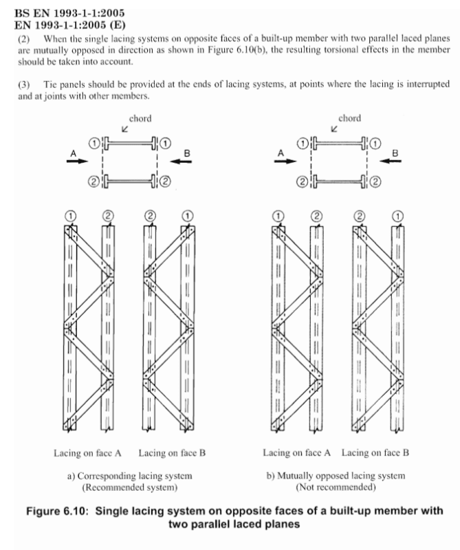
Studying Eurocode 1993 1-1, i've found, in topic 6.4.2.2 (Constructional details), the recommendation about the orientation of the lacing planes on built-up columns shown below.

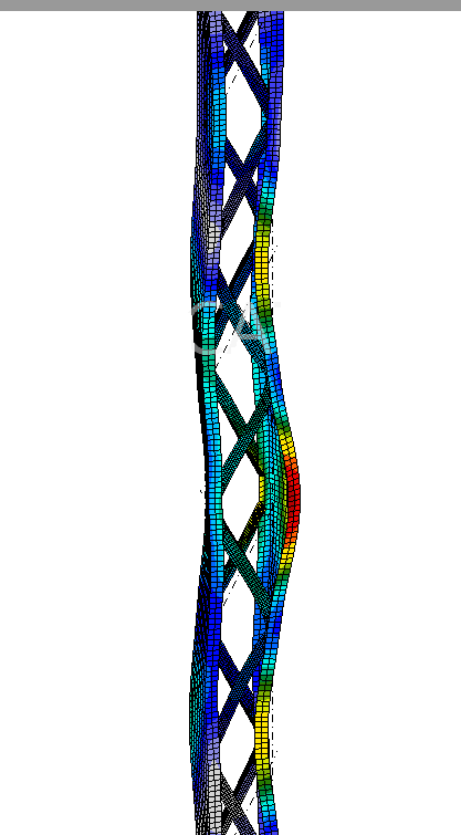
I've never used this mutually opposed lacing system but i see it in my region with a reasonable frequency and i think nobody consider the torsional effects. I'm planning to do some research on this topic and maybe write a paper about it if i verify that the reduction on member strength due to this torsional effects is too great and if there's no paper already written on the subject. Is anyone aware of such paper or has analyzed a structure of such type?
If Eurocode brings a recommendation about it and says that there are torsional effects, i think that someone has done research on the topic but i couldn't find it. Also, Would you suggest a frame analysis with the diagonal ends offset or a complete FEM analysis.
Thank you in advance.
Studying Eurocode 1993 1-1, i've found, in topic 6.4.2.2 (Constructional details), the recommendation about the orientation of the lacing planes on built-up columns shown below.

I've never used this mutually opposed lacing system but i see it in my region with a reasonable frequency and i think nobody consider the torsional effects. I'm planning to do some research on this topic and maybe write a paper about it if i verify that the reduction on member strength due to this torsional effects is too great and if there's no paper already written on the subject. Is anyone aware of such paper or has analyzed a structure of such type?
If Eurocode brings a recommendation about it and says that there are torsional effects, i think that someone has done research on the topic but i couldn't find it. Also, Would you suggest a frame analysis with the diagonal ends offset or a complete FEM analysis.
Thank you in advance.


