Eng-Tips is the largest engineering community on the Internet

Intelligent Work Forums for Engineering Professionals

Translation modifier questions 4

Status
Not open for further replies.

sendithard

Industrial
Aug 26, 2021
166
0
0
US
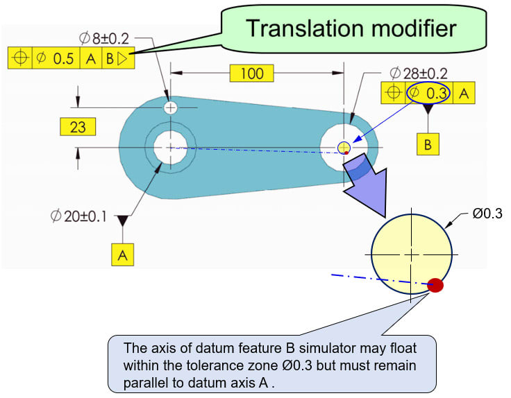
I didn't understand the translation modifier until I simply watched Don Day's tec ease video on it recently:

Makes sense that a datum fixed by a basic dimension could not be properly located to the actual feature location so shit could not be stable.

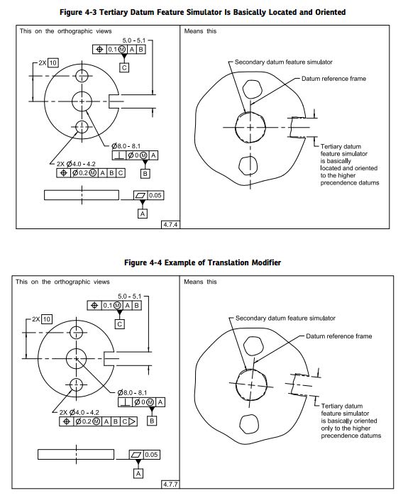
My question is b/c you are placing this modifier after its own Datum Symbol if the Datum location was spelled out with Basic dimensions in both X and Y locations(and not a centerline like Don's video), I assume this could translate in both directions...and AS much as possible, potentially not adhering to an engineers idea when they place a basic in two directions. Either my idea of how wrong this could go is indeed wrong...or the engineer understands what they are doing with this modifier...this is a modifier I'd be happy to not ever use....unless I could tolerance the modifier itself, which is quite odd.

Just looking for some discourse on this odd section in the standard, thanks as always.
 
Replies continue below

Recommended for you

The translation modifier in this use is implied on a "you know what it is supposed to mean" basis. Technically one does a constraints analysis and the translation modifier indicates that already controlled degrees of freedom are ignored for the datum feature with the translation modifier.

One can make this explicit by defining the datum feature as an oriented width to indicate that only the tangential control is in effect, ignoring the radial control.

I haven't seen a practical application where the datum feature allowed to translate is also a close-fit hole/pin combination except when using a diamond pin as a fixed datum feature that only contacts the width of a hole, which is explicitly represented in the second method - no translation modifier required. This is particularly true of RFS - no expanding pins at precise locations to accept the feature which then move when used as a datum feature.

Why does the translation modifier exist? I think it is so CMM computers can read the callout. A graphical depiction is more difficult for CMM software to manage. One could also use a customized datum reference frame which is explicit and is machine readable, but that's more work for the drafter.
 
sendithard,
In the tec-ease video, since datum hole B is secondary after the primary datum hole A, the directions X and Y are not even established (relative to the rest of the part) until datum B is simulated. Only after rotation about datum axis A is constrained (by simulation of datum B) you can talk meaningfully about X and Y directions. The translation invoked by the modifier takes place before that (during datum B simulation).

Can you sketch an example of where you think the situation will be problematic?
 
Burunduk

Please correct me if my understanding is not right on this case.

The translation on this case does not “translate in both directions” as OP said, and it does not mean to move along the X-axis only, instead the axis of datum feature B simulator may float within the tolerance zone Ø0.3 which is specified and established by datum feature A (as shown below), the most important is the axis of datum feature B simulator must remain parallel to datum axis A.

2023-01-27_nfug5u.jpg


Season
 
SeasonLee,
You are right that the axis of datum feature simulator B must remain parallel to datum A, as it is always the case. The translation modifier means that the distance between the datum feature simulators (100) is adjustable to accommodate for the position deviation of datum feature B relative to datum axis A. It should be adjustable at least in the range of 99.85-100.15 due to the ø0.3 position tolerance (practically it doesn't really matter if the range is greater and goes beyond these limits).
Since the datum simulation for B takes place before the rotation around A is locked, the direction of translation (or adjustment) as shown in the image is not really meaningful (it is shown translated below the horizontal line connecting the holes but could have been rotated otherwise). The axis of datum feature simulator B can rotate 360° around datum axis A. Only after the simulator for datum B is engaged with datum hole B, the directions which are horizontal (Could be X) and vertical (could be Y) in the image, are defined by the established datum reference frame, and are meaningful for the orientation of the part that is constrained relative to it.
 
SeasonLee,
Here is another way to look at it (maybe simpler):
Since the datum reference frame is established by the datum feature simulators and datums, the direction of the plane connecting datum axes A and B defines X. Then, any translation is in the X direction, by definition.
 
Yes, this is what I said "to move along the X-axis", my understanding is this is only one of the possible translations, as long as the translation happened within the tolerance zone Ø0.3 is accepted.

Season
 
The image in the 27 Jan 23 05:41 is misleading. The mutual axis between A and B is always exactly aligned in the [A|B} datum reference frame. The ability for datum feature B to take up space is solely due to being closer or farther from [A] and tilting out out parallelism to [A]. It cannot be entirely shifted in any other direction.

Only if the features in the diagram were held in some mutual alignment to another feature that controlled orientation (rotation in the plane nominally perpendicular to the features used as datum features [A] and ) could the situation be as shown.

Even then, once the evaluation as [A|B} is done that rotation fixation is gone and A and B are exactly aligned no matter where they were in some other datum reference frame.
 
3DDave

Thanks for your comments.
Would you mind to show us a scketch or diagram how this translation works, I am glad to learn where I went wrong.

Season
 
I think this subject has been discussed here on this forum at least few dozen times. If you search for fig 4-19 or 4-32(b) or even for Bill Tandler article you might find good sources.

Per Bill Tandler (see attached link in the above thread)
"How useful is the Transaltion modifier"? VERY
But the number of useful instances will be small.


Another excerpt of his opinion --see below

"The new "Translation" modifier, which may be appended to a Datum Feature label in a Feature Control Frame, specifies that the associated Datum Feature Simulator (and its associated Datum) shall be free to translate toward or away from the primary axis or origin of a partially established Datum Reference Frame during the Datum Reference Frame constraining step. Availability of the "Translation" modifier allows the Designer to clearly distinguish between the function of a "clocking" Datum Feature and an "aligning" Datum Feature, namely between a feature which constrains rotational degrees of freedom by virtue of its location (clocking) and one which does so by virtue of its orientation (alignment).

Referring to Fig. 4-32 p.74 in the 2009 Standard, lack of a Translation modifier in alternative a) makes Datum Feature B a "clocking" Datum Feature, in other words, one whose orientation has no impact on roll constraint.

The presence of a Translation modifier in alternative b) now makes Datum Feature B an "aligning" Datum
Feature, in other words one whose orientation determines the alignment of the remaining axes of the Datum Reference Frame. Note: Both illustrations on the right in Fig. 4-32 are intended to represent a real part.

Unfortunately the two bores are not "squiggly" and therefore do not look very real, but they are understood to be. Even more unfortunately the bore pattern in alternative b) is not rotated slightly clockwise as it must naturally be if the part in alternative b) is the same as that in a), which is absolutely the intent."
 
@Burunduk,

Thanks for your explanation...I feel my understanding of GDT should have seen this so I'm disappointed in myself for not realizing that rotation is not acquired until B is solved. Therefore, B simply can be within the limits regardless where that pin gage sits in a 360 deg circle. Another humbling moment, thanks.
 
Hi All,

Here's a sketch of what generally happens on the secondary datum feature when its location is not perfect. This is purely a 2D depiction - I haven't tried to include the effect of orientation error (tilt).

TranslationModifier_k0ktpm.png


The circles represent the true geometric counterpart (TGC) pin.

Without the translation modifier, the TGC pin is constrained to be located at true position (red crosshair). As it expands, it contacts the hole at 2 points on one side of the hole. These 2 points are not opposed at all, giving unstable contact that doesn't constrain the clocking rotation very well. If the hole is extremely round, this effect is even worse.

With the translation modifier, the pin is allowed to translate and make full (3 point) contact with the hole. This contact constrains the clocking rotation much more effectively. I would say that this is the main advantage of the translation modifier.

Evan Janeshewski

Axymetrix Quality Engineering Inc.
 
In order to not be opposed at all the normal vectors at the points of contact would need to be parallel, a condition that is not possible for contact with a radius as those normal vectors of contact are also radial to the expanding feature. To be parallel the radius would be infinite, which cannot happen.

A slightly better example is a cusp such that there are two stable positions without translation, but then there is also the possibility for horizontally opposed cusps so that even with translation there are two stable positions.
 
Considering the image pmarc posted above,
If the key component which fits in the groove in the assembly this part is used at is fixed/constrained relative to the center axis of the bore in which datum feature A mates, then the option without the translation modifier is preferable, and it is more restrictive.
If the key is inserted into the groove manually without constraints, then the translation modifier can be used, and this option is more permissive, because more variation is allowed for the orientation of the 2 holes.
Note that the order and nature of constraints of degrees of freedom are identical in both cases, therefore the modifier cannot be substituted by other tools such a customized DRF for its purpose.
 
Good summary, Burunduk. A small addition would be that in both cases to make C at RMB valid choice based on function, the mating component would have to be press fit in the groove or would need to expand during the assembly to achieve the full possible contact wit the groove.

Also, I fully agree that the customized DRF option wouldn't be a substitute.
 
Status
Not open for further replies.
Back
Top