Continue to Site

Eng-Tips is the largest engineering community on the Internet

Intelligent Work Forums for Engineering Professionals

  • Congratulations KootK on being selected by the Eng-Tips community for having the most helpful posts in the forums last week. Way to Go!

Translation modifier questions 4

Status
Not open for further replies.

sendithard

Industrial
Aug 26, 2021
178
I didn't understand the translation modifier until I simply watched Don Day's tec ease video on it recently:

Makes sense that a datum fixed by a basic dimension could not be properly located to the actual feature location so shit could not be stable.

My question is b/c you are placing this modifier after its own Datum Symbol if the Datum location was spelled out with Basic dimensions in both X and Y locations(and not a centerline like Don's video), I assume this could translate in both directions...and AS much as possible, potentially not adhering to an engineers idea when they place a basic in two directions. Either my idea of how wrong this could go is indeed wrong...or the engineer understands what they are doing with this modifier...this is a modifier I'd be happy to not ever use....unless I could tolerance the modifier itself, which is quite odd.

Just looking for some discourse on this odd section in the standard, thanks as always.
 
Replies continue below

Recommended for you

Burunduk, The customized datum reference frame, which was designed for that exact case, can be used instead. Unlike the translation modifier, the customized datum reference frame is explicit about the exact nature of the control.

"If the key is inserted into the groove manually without constraints, " then there is no relationship at all. It doesn't control rotation or translation of the assembly having a relationship to the slot alone and no other feature in the assembly.
 
3DDave,
Write down the degrees of freedom each datum feature and its corresponding datum feature simulator constrain in figure 4-3 posted above by pmarc.
Then write it down for figure 4-4 which follows it.
See any difference?

"It doesn't control rotation or translation of the assembly having a relationship to the slot alone and no other feature in the assembly."
If it has a relationship to the slot, it has a relationship to at least one component of the assembly. It may be used to constrain and relate other components to the mechanism afterward.
 
See any difference? Yes. What is your point? Write down the customized DRF for each case. See how that control works?

The translation modifier control is a subset of the explicit customized datum reference frame.

It's your example - the part is in the assembly, and you added a key that is not linked to any other component. Probably that key will fall out.
 
Hi All,

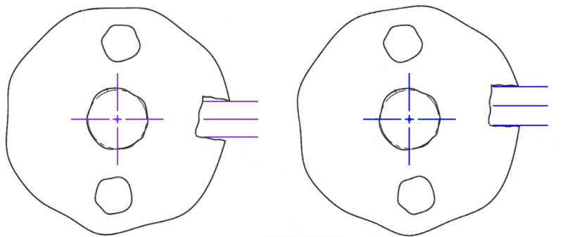
I noticed that the effect of the translation modifier is obscured a bit in Figure 4-3 and 4-4 because the as-produced part geometry is different in each figure. Here is a sketch of the TGC without translation (left) and with translation (right) using the as-produced part geometry from Figure 4-4:

51_Fig_4-4_Translation_Comparison_pi11si.png


I agree with Burunduk that this effect cannot be duplicated with a customized datum reference frame - it's just not the same thing. In both cases, the slot is constraining the same degree of freedom (w rotation).

Evan Janeshewski

Axymetrix Quality Engineering Inc.
 
That is the case only for the same order, which isn't a requirement. Instead of [A|B|C] for the first the second can be [A|C|B] with customization to decide if the Y direction is located from B or C.
 
3DDave said:
See any difference? Yes. What is your point?
Well, unfortunately I can't make my point now, because your answer should have been no. As long as you see a difference in degrees of freedom constraints that doesn't actually exist, you won't be convinced that the customized DRF can't replace the translation modifier.
The difference is in acceptance of variation (loosening the orientation requirement of the controlled pattern of 2 holes) not in how the degrees of freedom are constrained by each datum feature and its simulator.

"key that is not linked to any other component" - I didn't say it isn't linked to any other component. I said it is not constrained by any other component. For example, It could be connected to this component by press-fitting in the slot (unusual for a key and keyway, but possible with a different size tolerance on the slot width), and then used to drive some other component, which has only a loose enough relationship with any features of this part other than being linked to the slot through the key.
 
Driving is a linkage. That's how cams work. Linkage is a constraint. That's how constraints work. What doesn't work is being unable to deliver the tolerance chain loop to support your example. Saying the key touches nothing says there is no tolerance loop.

You have to be a drafter with no mechanism design experience.

I explained the difference in my reply to axym. You should read it.
 
I said the key could be press-fit to the slot and drive something.
"Saying the key touches nothing says there is no tolerance loop"
How can the key drive something if it touches nothing?
That's not what I said.

Your proposed scheme of changing the datum precedence order and adding customization won't work. The intent of the option with the translation modifier is still to let datum feature B, not C, stop the translational degrees of freedom in the two directions normal to datum axis A. Therefore in the two cases of figures 4-3 and 4-4 the B is what "Y direction is located from".
 
3DDave,

I hadn't even thought of changing the order. So the equivalent customized DRF for the translation modifier example in 4-4 would be |A[z,u,v]|C[w]|B[x,y]|. I suppose you're right - that would achieve the same constraint.

Evan Janeshewski

Axymetrix Quality Engineering Inc.
 
axym said:
So the equivalent customized DRF for the translation modifier example in 4-4 would be |A[z,u,v]|C[w]|B[x,y]
In that case, Datum feature simulator B would be required to be centered to datum C. Which will eliminate the offset adjustment between simulators that is allowed by the translation modifier and its intended effect on the controlled features.
This will not result in the same type of constraints.

Do not forget TGC requirements:
"(c) basic location relative to other true geometric counterparts for all the datum references in a feature control frame, unless a translation modifier or “movable datum target” symbol is specified"
 
" I said it is not constrained by any other component. "

That is literally saying it is not constrained. If it is required to touch another component in order to drive it that is a constraint. If that driven object has no relation to other features on the part through a tolerance loop then it doesn't need to be controlled.

4-3 vs. 4-4 are two of the cases Herb Voelcker proposed a scheme to deal with and eventually he proposed the customized datum reference construction method to solve that problem.

The translation modifier was proposed by CMM supporters who didn't like the idea of explicitly identifying the width of the feature as a datum feature. That translation is a proper subset of Voelcker's work didn't matter to them. Neither did the fact that in one callout the feature is identified as having a nominally fixed (BASIC) position and then is assumed to be mobile in the referencing callout.

Below is explicit and identical to the translation modifier in Figure 4-4 , for the planar face as datum feature A, the hole as datum feature B, and the slot as datum feature C.

custom__drf_syt9uy.png


Effectively the mating part/assembly for a translation modified (or via a custom datum reference frame inclusion) datum feature is a mechanism that needs to both expand uniformly and to move in only one direction, both possibly at the same time, but with significant rigidity in all other directions.

Even in this, however, the translation modifier is limited compared to a graphical depiction, which could show the acceptable path of the datum feature constraint as a function of where the datum feature is - the mating mechanism might be an expanding pin on a path that does not align with the center of the datum reference frame origin and might be linear, on an arc, or an arbitrary curve.

Physical datum feature simulators and true geometric counterparts are intended to stand in for the mating part and represent the limitations on how the mating part/assembly or function of the mating part/assembly is allowed to interact with the considered part. The datum references should reflect that interaction; usually they reflect some other scheme that is easier to inspect on a CMM often on the grounds of "stability" which the part often won't match in the assembly.
 
3DDave, here is a more traditional example to aid your understanding of the difference between a link and a constraint:
If you hammer a pin into a hole to make a press fit, is the pin constrained by the hole it is nailed into or by the clearance hole in the mating part?

Regarding your suggested alternative using the customized DRF, read the end of my reply to axym above, right before your last post.
 
Great edit, makes no difference. The basic location of a feature is per the feature's feature control frame, not references to it. If the FCF that references a feature says the width sets the rotation orientation only then there is no requirement for the location of that feature in the DRF. This is all explained in the Voelcker papers. You should look them up.

If there is clearance then (perhaps) there isn't a tolerance loop tied to the press fit is there? There is a separate tolerance loop at the next assembly, but that isn't in any way like the cases discussed here. Both are (separate) constraints on the fit and location of the pin and the amount of extension for the pin. If the location of the pin affects when the clearance goes away, then that is also a constraint that needs to be reflected in the analysis and the dimensioning and tolerancing.

Stay on topic with the examples at hand as a basis - show a mechanism where the key is linked to the two holes. but the location of the key midplane is not. Then use the customized datum reference frame I provided as that is the same as the translation modifier for this case.
 
"The basic location of a feature is per the feature's feature control frame, not references to it. If the FCF that references a feature says the width sets the rotation orientation only then there is no requirement for the location of that feature in the DRF"
I don't know what that means.
What I do know is that the basic location of the feature is per the basic dimensions.  The location of the datum feature simulator is per the rules governing mutual location between datum feature simulators (TGCs when speaking theoretically), therefore the translation/offset between the center plane of the expanding tab used as the simulator for the slot (C) and the center of the expanding pin used as the simulator for the  bore (B) is impossible without the translation modifier. If so, the customization of the DRF cannot reproduce the effect of this modifier.

I don't know the details about Voelker's proposal, and without them, it is impossible to estimate its feasibility in the context of the existing rules of Y14.5.  Maybe he also proposed to change the rules that apply to TGCs (datum simulation) or the conditions imposed by the customized DRF. You're the one who brought up his work, so it's up to you to link to that paper and clarify how it resolves the conflict with the rule you were pointed to.

You seem to miss the point of the pin example. The point was not to indicate that there is no "tolerance loop". When the pin is hammered into a hole for press fit, it is not constrained/influenced by the mating part with the clearance hole in that process. If there is a bore in the part used as the primary datum feature A for some position control and at a basic distance of X there is the press fit hole used as the secondary datum reference (B) in the A, B DRF only to lock rotation around datum axis A, the translation modifier can also be appropriate, and its function cannot be reproduced by customizing the DRF. Now make the logical connection to the case being discussed.
 
"I don't know what that means."

Clearly.

Voelcker's work result is the custom datum reference framework. If you need a tutorial his prior discussion will help you. It's up to you to do your own research. I doubt any of his information remains on line. It was before 2009 and, for example, the entire work of Dr. Chase has been removed from the Brigham Young University website; foundational work is often lost to the web. Perhaps you will get lucky.

Perhaps the note under 7.5.2 Requirements of True Geometric Counterparts?

Some of the requirements in (a) through (f) above are not applicable when a customized datum reference frame is specified.

Seems like 2018 clarified things a bit. Conflict resolved.
 
I expected way more than that from someone who confidently claimed that the customized DRF "was designed for that exact case".
The customized DRF was added in 2009. The note under TGC requirements was added only in the subsequent edition. Moreover, it does not clarify which requirements can be overridden and which stay intact. Can any of them be overridden, or is it up to the user to decide?
If Voelker's paper was published that long ago it could not be supported by the rules as it was way before that vague hint appeared in the last edition.
You are the one basing your position on his work, so it is up to you to dig up his paper and present the support for your claims.
The standard covers in details how the translation modifier manages this case. There is only a hint that translation may be allowed under the customized DRF simulation, and the solution doesn't come without reversing the datum precedence order in a way that is in contrast with the fundamentals of selecting that order. The datum precedence order generally corresponds to the number of degrees of freedom each datum feature simulator has to constrain. What you present as Voelker's solution, based on some mysterious paper that is no longer available, and you can't even name it, is questionable at best.
 
That the 2009 edition mischaracterized the Voelker proposal by ignoring it in a critical section is no surprise. I spoke with a number of people who decried at an ASME meeting following the publication that 2009 was a rush job. The problem being that they were in year 14 of a 10 year release cycle. Notice how they cut that to essentially 8 years to get 2018 out? They freeze inputs about a year ahead to do a public draft.

I can name it: Musing On Datums The Brown & Sharpe Publication of Precision Manufacturing; the pdf was created in May 2003.

Also:

DATUM SYNTAX AND SEMANTICS IN GEOMETRIC TOLERANCING
by
Herbert B. Voelcker
CORNELL UNIVERSITY
Ithaca, NY
May 2002

He wanted contributions of datum references in datum reference frames to be explicit instead of using an endless number of special cases. Of course the committee added another special case at the same time.

There is more than a hint. In one case orientation is overridden and in the next translation is. If you need spoon feeding find the Voelker papers. I'll warn you, the committee dumbed it down a bit so they had to add the CSYS symbol to compensate, which does make the standard's version easier to read.

That it took the committee that long to fix the problem they created is also no surprise. They were so intent on dealing with datum feature simulators and true geometric counterparts based on all the old material they dealt with the new material poorly.
 
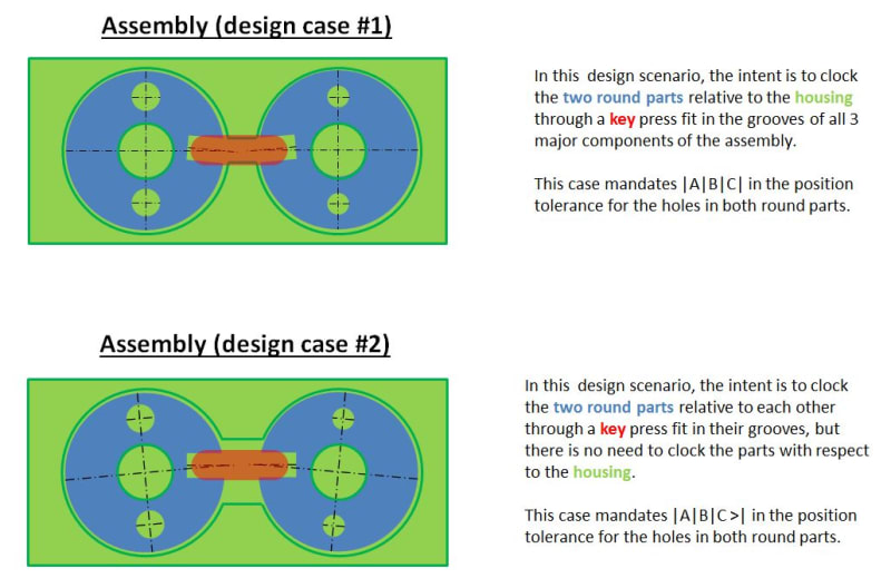
For what it's worth, for the part similar to the one shown in figs. 4-3 and 4-4, this is how I would envision two design cases in which the usage of the translation modifier would and would not be the correct choice. Of course this is just to show the idea - real assemblies could look totally different.

aaaaaaaaaa_ishyee.jpg


Apart from that, I still fully agree with Burunduk that the proposed alternative DRF |A[z,u,v]|C[w]|B[x,y]| is not equivalent to |A|B|C>|. The note at the end of 7.5.2 in Y14.5-2018 is, unfortunately, an example of how things should not be worded in this and any standard. It is super ambiguous for the reasons Burunduk provided. Additionally, one of the customized-DRF-related figures in the standard, 7-57, shows that the two TGCs playing role in the customization of the DRF are at basic distance with respect to each other. So does it mean that now users of the standard are free to arbitrarily choose which of the rules for TGCs given in 7.5.2 are applicable or not for customized DRFs?
 
pmarc,

So, if I say -
1) put the part datum feature A flat onto the CMM surface. Set that as Z0
2) use the orientation of the midplane of datum feature C as the X-axis orientation
3) set the origin for X and Y basic dimensions from the center of datum feature B

that you will be both unable to do that?

and it will end up with an orientation entirely different from

1) put the part datum feature A flat onto the CMM surface. Set that as Z0
2) set the origin for X and Y basic dimensions from the center of datum feature B
3) rotate the part until the orientation of the midplane of datum feature C is parallel with the X-axis

???

If you don't like the note did you complain about it at the public draft release or any of the meetings where that note was discussed? I would have, if the ASME members bothered to announce the release in advance of the comment period someplace other than their jumble of "you guess when" notices. Not that I'm bitter. I';m sure all other members also down-voted that note, right?

Only if one ignores that the first example has a datum translation and the second allows changing the datum orientation relative to other datum feature references can one conclude that customized datum references don't function.
 
I am not sure what "entirely different" exactly means to you, but in my opinion the two procedures, assuming I am reading them correctly, will result in different part-to-TGC relationships, therefore they might lead to different position error readings for the two holes.

The pictures below assume that the TGCs of B and C are always perfectly located to each other.

aaaaaaaaa_xy6lwv.png
 
Status
Not open for further replies.

Part and Inventory Search

Sponsor