Continue to Site

Eng-Tips is the largest engineering community on the Internet

Intelligent Work Forums for Engineering Professionals

  • Congratulations KootK on being selected by the Eng-Tips community for having the most helpful posts in the forums last week. Way to Go!

Customized DRF instead of a Translation Modifier 1

Status
Not open for further replies.

Burunduk

Mechanical
May 2, 2019
2,339
During a recent discussion that developed in thread1103-501700 , claims were made that at every place where the Translation Modifier is used, the Customized Datum Reference Frame tool can be used instead.
Here is an excerpt of the argumentation:

3DDave said:
The point is that customized datum reference frames are a proper superset of which the translation modifier is a tiny part. That there is no function available via the translation modifier that is not contained within the customized datum reference frame capability. That the control of acceptable variation by the more capable approach is identical to the more limited approach with the correct syntax.

Other opinions that were expressed suggested otherwise:
Evan said:
In some cases (such as the plane-hole-slot case discussed earlier in the thread) the same DRF can be achieved using either tool but this is not true in the majority of cases.

I'm interested in clarifying the issue.
Below is a drawing example that uses the Translation Modifier tool.
The ⌀25H7 bore is the locating feature of this component in its functional assembly, and it also sets its initial orientation. It aligns to a mating shaft with a "sliding" clearance fit of H7/g6 (hole basis). The ⌀3P7 hole is intended to fit with a pin that will be assembled into it with an Interference fit of P7/h6 (shaft basis). The pin will contact a radial slot on the mating part to lock the rotation about the axis of the bore, to do the "clocking".
If you were to duplicate the effect of the Translation Modifier applied to datum feature B by using a Customized DRF, how would you go about it? What would the customized datum reference frame look like, and how would it override the default degrees of freedom constrained by datum features A primary, B secondary?
If you think this idea would not work and the translation modifier should be kept, please explain why.
I would appreciate everyone's opinions.
Thank you.
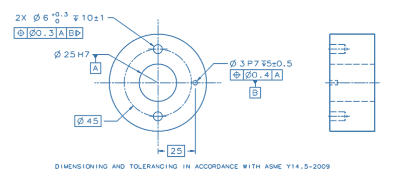
translation_mod._dwg._fzbed6.png
 
Replies continue below

Recommended for you

A search for "tertiary datum problem" turned up the name Herb Voelcker. Talk about providing extensive solutions to problems people don't have and making more problems at the same time.

3DDave, that's interesting.
Now you are presenting Voelcker as the initiator of the original customized datum reference frame "superset" which the committee never managed to implement as he intended. Have you completely changed your mind?
 
Changed my mind about what? I still see no practical application for either translation or customized datum reference frames.

It has been allowable to graphically depict the degree of freedom that a datum feature controls as shown for bidirectional/othogonal position tolerances or notes.

In you example of mating with a slot - the iteraction in radial and tangential dirctions are independent. You lose out some of the available tolerance by using a diameter that ties them together. Separate tolerances would allow more usable parts to be accepted.
 
Loosening the tolerance beyond ⌀0.4 for what may be a CNC-drilled hole might not benefit the acceptance rates.
What can be beneficial is communicating the mobile location for the clocking datum feature simulator to better represent the functional constraints and remove an unnecessary limitation that may affect the stability of measurement.

You don't see the contrast between your old and recent statements?
When you said in thread1103-501700:
"That the 2009 edition mischaracterized the Voelker proposal by ignoring it in a critical section is no surprise", and:
"He wanted contributions of datum references in datum reference frames to be explicit instead of using an endless number of special cases" it didn't sound like you believe that his proposals offered solutions to non-existent problems and created more problems by that.

However, the truth is that his proposed solutions, at least judging by the paper:
"DATUM SYNTAX AND SEMANTICS IN GEOMETRIC TOLERANCING" (the link to which was provided here by Necsius) do not address a problem that is relevant following the 2009 edition of Y14.5. Moreover, they are certainly not superior to the ones that were implemented. The "tertiary datum problem" is illustrated in Figure 3 of that paper, addressing the interpretation of the example shown in Figure 2. Per the new datum simulation defaults that were clearly described in a dedicated section (4.5.2 in 2009, 7.5.2 in 2018) the current solution to the problem of Figure 3 is the option shown as 3a - which is now the default interpretation. Per the 94' version it was 3b, which often led to the indecision between 3b-1 and 3b-2, and this was the essence of the "tertiary datum problem".
He proposed solutions for overriding the defaults, but the two solutions he offered were ineffective.
One of them, according to his own words, was - "verbose, and perhaps 'too fancy' for some detailers and shop-floor people".
The other one didn't make sense, because it only provided a tool to eliminate both the orientation and location constraints between simulators of datums used to establish the same datum reference frame. At the end of that paper, he offered a non-graphical method to define a coordinate system by using complex and cumbersome symbology.
Any connection between his proposals and the customized datum reference frame tool is only tangential, which makes your statement from thread1103-501700 : "Voelcker's work result is the custom datum reference framework" (29 Jan 23 12:16) erroneous.

You still haven't proposed a valid solution to reproduce the effect of the translation modifier in my example by the customized DRF tool.
 
3DDave said:
I still see no practical application for either translation or customized datum reference frames.

As CH joined the translation vs. customized DRF discussion, this reminded me of an old thread started by him back in 2010 in which he wanted to use a square feature to establish a datum axis for a runout tolerance to be applied to a cylindrical feature of a shaft:

If the square was used as primary datum feature, this, by default, would constrain 5 DOFs of the part [x,y,u,v,w]. I can imagine that some could still say that this wouldn't disallow using the square to establish datum axis for the runout FCF (maybe as an extension of principles?), so let's imagine that the shaft has an additional hole nominally parallel to the datum axis but offset from it that the designer would like to freely orbit around the datum square as long as it stays within intented distance limits from the axis. For that, wouldn't referencing A as |A[x,y,u,v]| in the position FCF for the hole allow to accomplish that functional objective?

If the answer is yes, then I would have a question to Burunduk (which is related to the topic that was discussed in the other thread where he said that it would generally be a bad idea to use/explore the concept of a point, line, plane, or combination thereof to define/describe a datum). What exactly would the customization of A in the position FCF change in terms of the point/line/plane combination?

Side note: In this and some recent threads a lot has been said about a need to simplify the GD&T language to make it more straightforward for its users. In this context, wouldn't it make sense to label 6 DOFs as [Tx,Ty,Tz,Rx,Ry,Rz] instead of [x,y,z,u,v,w]?
 
pmarc,
The answer to your first question - "wouldn't referencing A as |A[x,y,u,v]| in the position FCF for the hole allow to accomplish that functional objective?"
is yes.

As for the question addressed to me mentioning the "point/line/plane combination", if it is in the context of "revolute invariance class" that you mentioned in thread1103-501342, where a superfluous datum point is added based on the combination of a datum axis related to one datum feature and a datum plane related to another datum feature referenced in the same feature control frame, then I'm not sure how it is related to customization of the square datum feature A.
The way I see it, the square datum feature referenced in CH's total runout example as A-B provides two datum planes (mutually related center planes maintaining a basic right-angle) and a datum line at their intersection. These are two of the three planes of the DRF and one of the axes of the DRF-related coordinate system. The customization of datum reference A-B simply unlocks the orientation of the 2 planes relative to the actual square datum feature.
 
Burunduk,

I wasn't really thinking about revolute invariance class. In the case I described, the customization results in "reduction" of the line-on-a-plane combination to a line-only scenario. This is what makes the case no different than the situation with a regular cylindrical feature used as primary datum feature.
 
pmarc,
I guess it's not wrong to describe it that way (line-only).
But if it's not about my comment on revolute invariance class, then I have no idea what you referred to when you mentioned that I "said that it would generally be a bad idea to use/explore the concept of a point, line, plane, or combination thereof to define/describe a datum". Can you clarify?
 
Burunduk,
I just thought you would find the explanation of customization in terms of combination of point/line/plane (point is not involved in my example) interesting and worth exploring it further.

I won't say that in my mind looking at the datum theory (part of which the DRF customization is) from this angle solves all the problems that the theory has today but I think this might lead to some interesting observations and conclusions that might help bring us closer to the development of a complete and mathematically sound set of rules for datums, TGCs, relationship between them, etc.
 
pmarc, I am intrigued and find it worth exploring. But I'm not quite sure that I see what you see there, just yet.
According to my answer, the datum associated with the square datum feature would be two normal planes and a straight line at their intersection, with the orientation of the two planes unlocked by the customization. According to your answer, the customization reduces the datum to line-only, similarly to the axis of a cylinder. But that line, just like the axis of a cylinder, is anyway associated with 2 planes of the datum reference frame intersecting at it - so, I don't see a substantial difference between the two descriptions. For me, it is still more direct to look at it from the perspective of degrees of freedom being constrained or unconstrained. But, I would be glad to get to know your take on it.
 
Burunduk,
The approach I mentioned also looks from the perspective of degrees of freedom being constrained and unconstrained. It just creates general categories of the DOF-constraint cases that different real life scenarios may be described by. That is why they are called invariance classes.

As an example, the square feature might be a parallelogram or a complex curved shape instead but they would all end up in the same ability of the DRF to translate and rotate. In your approach users will have to accept the fact that in all 3 cases there are two planes and an line of intersection of the planes that the DRF needs then to be associated with in order to identify how many DOFs and which it has left unconstrained for the DRF. I am not saying it wouldn't still be far more intuitive for people than the invariance class approach, I am just not sure it would be easier to mathematize.

In the end, I am yet still to convince myself that one of the two methods is better than the other. Perhaps they always give the same results, just coming from different angles? Or maybe there is a different, more elegant, way to describe this stuff?
 
pmarc,
By creating categories for DOF constraint cases per datum feature geometry, are you essentially talking about something comparable with figure 7-3 of ASME Y14.5-2018 (4-3 in 2009)? Including possibly more than just the primary datum feature?
 
That figure is good for new users as a wall-chart type thing to get used to the basic cases such as the planar, cylindrical, and conical. It seems impossible to categorize all the special cases even for only the primary datum feature, especially if "common datum features", patterns of features, and different datum features that can be defined by datum targets are to be included.

Instead of categorization, I would try to come up with a method of directly establishing the planes and coordinate axes of the datum reference frame from the feature geometries and their DOF constraining abilities. For example, whenever linear movement is constrained by a feature by the virtue of its geometry and precedence, a plane of the datum reference frame is established normal to the direction of the constrained movement (translational DOF).
 
Burunduk said:
That figure is good for new users as a wall-chart type thing to get used to the basic cases such as the planar, cylindrical, and conical. It seems impossible to categorize all the special cases even for only the primary datum feature, especially if "common datum features", patterns of features, and different datum features that can be defined by datum targets are to be included.

I didn't say it would be this figure and this figure only. Also notice that the current figure lists all possible invariance classes of a primary datum feature. Other real life cases, including those that use primary, secondary, or tertiary patterns of features or datum targets to establish DRF, can be reduced down to these 6 invariance classes.


Burunduk said:
For example, whenever linear movement is constrained by a feature by the virtue of its geometry and precedence, a plane of the datum reference frame is established normal to the direction of the constrained movement (translational DOF).

So let's take a simple example of a planar bottom surface (primary datum feature A) of a rectangular block that has two holes drilled normal to the surface A. If I understand your recommendation correctly, this would establish a single plane of the DRF only and some lower order of precedence datum feature(s) would be needed to establish the remaining two planes of the DRF, right?

If yes, wouldn't that technically mean that in the absense of the two remaining planes of the DRF I would be left without a rectangular coordinate system relative to which I could report coordinates of the axes of the holes in the pattern to analyze, for example, spacing between the holes?

Per the approach I am describing/proposing, the DRF always consisits of all 3 mutually perpendicular planes, regardless of the number of datum feature references. In the case of the rectangular block with holes, the DRF would simply be allowed to freely translate and rotate in the datum plane A so that any coordinate system (optimized or not optimized) could be selected to report the hole axes coordinates.
 
pmarc,
I don't think I misunderstood you about the level of resemblance between what you are describing and fig. 7-3. Note that when suggesting that it would be comparable to it, I asked: "Including possibly more than just the primary datum feature?"
Unless I'm missing something, I don't see how that figure lists "all possible invariance classes of a primary datum feature". It doesn't list a flat taper for example (for dovetail type datum features) or a pattern of holes, or offset non-opposed parallel planes as a "common datum feature", and I could probably come up with many others. That's why I said "It seems impossible to categorize all the special cases even for only the primary datum feature". So, I am very skeptic that the "invariance classes" can be inclusive enough to cover all special cases for more than one datum reference. BTW, why "6 invariance classes"? There are already 7 rows (a-g) of the 7-3 table and more could be added.

pmarc said:
So let's take a simple example of a planar bottom surface (primary datum feature A) of a rectangular block that has two holes drilled normal to the surface A. If I understand your recommendation correctly, this would establish a single plane of the DRF only and some lower order of precedence datum feature(s) would be needed to establish the remaining two planes of the DRF, right?

No, I always view the datum reference or references in a feature control frame, regardless of their number - one two, or three, as establishing a datum reference frame, which is 3 orthogonal planes by definition. I would say the planar bottom surface as the primary and only datum feature establishes a plane of the DRF in the sense that it is related to it by at least 3 points of contact. The other 2 planes of the DRF are only required to be perpendicular to the one that acts as datum plane A and complete that system. What I say is that for the general case, including when the exact manner that the relation to the DRF occurs is less obvious, the ability of the feature to immobilize a translational degree of freedom could be used to invoke the connection to a plane normal to that direction, as part of a defined DRF establishment method. Such a method could replace the need to place everything into boxes a-la fig. 7-3 on the way to the DRF.
 
Burunduk said:
Unless I'm missing something, I don't see how that figure lists "all possible invariance classes of a primary datum feature". It doesn't list a flat taper for example (for dovetail type datum features) or a pattern of holes, or offset non-opposed parallel planes as a "common datum feature", and I could probably come up with many others.

Inv. Class of flat taper = Prismatic = a line on a plane = 5 DOFs constrained = 2 translations and 3 rotations = fig. 7-3(f)

Inv. Class of pattern of holes (I assume you mean offset parallel holes) = same as above

Inv. Class of offset non-opposed parallel planes = Planar = plane = 3 DOFs constrained = 1 translation and 2 rotations = fig. 7-3(a)


Burunduk said:
BTW, why "6 invariance classes"? There are already 7 rows (a-g) of the 7-3 table and more could be added.

Because (a) and (b) are no different. Both result in a Planar invariance class, therefore there could be just a single row for them (maybe with two examples of datums features).


Burunduk said:
So, I am very skeptic that the "invariance classes" can be inclusive enough to cover all special cases for more than one datum reference.

Have faith. ;-)
 
Ok, then, if I understand correctly:
The total amount of degrees of freedom constrained and specifically the amount of each type (translation/rotation) being constrained decides the invariance class for a primary datum feature, and similarly for a set of more than one datum feature referenced in a feature control frame. Is this the approach? Sounds like the determination of degrees of freedom constrained and unconstrained drives the rest of the process - so far similarly to the idea I proposed. But what is the rest of the process in your case? In my case, it is the direct establishment of the DRF as the origin of the tolerance zone's location and orientation definition.
In your case, it seems to drive classification. Once any special case has been classified according to its invariance class, what's then?
 
The DRF is associated with what figure 7-3 calls "datum". This allows to determine the number of locked and unlocked degrees of freedom of the DRF. Then the tolerance zones are oriented and located from the DRF. So I guess it is no different than in your case.
 
I got lost.
What comes first, second, third etc.
Do we first determine the number of DOF constraints of each type to classify the datum feature or set of datum features per invariance classes?(I think so, as I don't see any easily distinguishable similarity other than DOF constraints between a flat taper, a pattern of offset parallel holes, and the "linear extruded shape" of 7-3(f)) Then do we determine the datum/datums according to the invariance class? Then the datum "allows to determine the number of locked and unlocked degrees of freedom of the DRF"?? But we've already been there! Then finally do we get to establish the DRF from the datums as we are doing today? But what did we gain?
 
The answer to all your questions except the last one is yes.

For the last question, as I already mentioned a few replies ago, I am still yet to convince myself if there is a substantial gain in thinking in the "invariance class way".

In the example that made me start our conversation (a shaft with a square hole establishing datum axis for a runout tolerance or for a position tolerance of a hole) the difference would be that instead of specifying the degrees of freedom constrained by the square datum feature in order to say which of DOFs are not to be constrained, one could put a shorter designation, such as [AX] for axis or [LI] for line, to state that the datum feature is to act no different than a regular cylindrical datum feature.

Would this provide any advantage? Would this be a workable approach in general? I don't have answers to these questions yet.

What I think though, is that it would at least match the current Y14.5 definition of datum and would make the definition of DRF more understandable for cases where one is not able to directly establish all 3 planes of the DRF and is left with wondering how is it possible that, for example, a single planar datum feature is able to establish 3 mutually perpendicular planes of the DRF.

BTW: To clarify, the approach I am describing is not my invention. It is heavily influenced by ISO standard for datums and datum systems (ISO 5459).
 
Status
Not open for further replies.

Part and Inventory Search

Sponsor