Continue to Site

Eng-Tips is the largest engineering community on the Internet

Intelligent Work Forums for Engineering Professionals

  • Congratulations KootK on being selected by the Eng-Tips community for having the most helpful posts in the forums last week. Way to Go!

Customized DRF instead of a Translation Modifier 1

Status
Not open for further replies.

Burunduk

Mechanical
May 2, 2019
2,358
During a recent discussion that developed in thread1103-501700 , claims were made that at every place where the Translation Modifier is used, the Customized Datum Reference Frame tool can be used instead.
Here is an excerpt of the argumentation:

3DDave said:
The point is that customized datum reference frames are a proper superset of which the translation modifier is a tiny part. That there is no function available via the translation modifier that is not contained within the customized datum reference frame capability. That the control of acceptable variation by the more capable approach is identical to the more limited approach with the correct syntax.

Other opinions that were expressed suggested otherwise:
Evan said:
In some cases (such as the plane-hole-slot case discussed earlier in the thread) the same DRF can be achieved using either tool but this is not true in the majority of cases.

I'm interested in clarifying the issue.
Below is a drawing example that uses the Translation Modifier tool.
The ⌀25H7 bore is the locating feature of this component in its functional assembly, and it also sets its initial orientation. It aligns to a mating shaft with a "sliding" clearance fit of H7/g6 (hole basis). The ⌀3P7 hole is intended to fit with a pin that will be assembled into it with an Interference fit of P7/h6 (shaft basis). The pin will contact a radial slot on the mating part to lock the rotation about the axis of the bore, to do the "clocking".
If you were to duplicate the effect of the Translation Modifier applied to datum feature B by using a Customized DRF, how would you go about it? What would the customized datum reference frame look like, and how would it override the default degrees of freedom constrained by datum features A primary, B secondary?
If you think this idea would not work and the translation modifier should be kept, please explain why.
I would appreciate everyone's opinions.
Thank you.
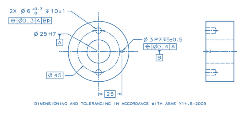
translation_mod._dwg._fzbed6.png
 
Replies continue below

Recommended for you

pmarc said:
instead of specifying the degrees of freedom constrained by the square datum feature in order to say which of DOFs are not to be constrained, one could put a shorter designation, such as [AX] for axis or [LI] for line, to state that the datum feature is to act no different than a regular cylindrical datum feature.

So, that's the innovation.
For such shortcut to be used effectively,
Both the drawing maker and user need to understand the difference between the constrained degrees of freedom between the cases when the datum is an axis and when the datum is two planes and a line.
For what it's worth, I'm not sure that I am always able to tell the degrees of freedom constrained just by knowing what the datum is. I guess I can tell for the basic cases, that if the datum is a plane that would be 2 rotations and 1 translation, when it's an axis it's 2 translations and 2 rotations, when it's a point derived from a simple sphere it would only be 3 translations. But I got used to that only after looking many times at the feature's geometry, and imagining how the feature, when maintained in contact or gripped by what the standard calls true geometric counterpart, resists manipulations in different directions.

As for what the datum is - sometimes it's intuitive and sometimes it's not. Sometimes the datum could be described differently than in the standard, and it wouldn't make any difference for constraints of DOF and establishment of DRF.
That's why I am not a fan of analyzing the datum. See the comparison between the standard's fig. 7-3 and another version from Geotol, which I posted in thread1103-498663. Does it matter if for a cone for example, the datum is an axis and a point like in the standard, or an axis and a plane as in Geotol's version?
 
You're making good point with referring to the GeoTol figure. That's all I am able to say at the moment.
 
The 2018 Figure 7-3 chart is fundamentally of machine elements - except it is missing helical movement that ties rotation to translation along an axis and extrusions along curved paths which constrain 5 degrees of freedom. The former are used in the clocking of items such as lids and the latter as ball-bearing races. Sometimes the latter is exemplified by a toroidal invariant class surface.

Not sure I care for the hijacking of "invariant class" to mean something entirely different than was originally intended, but that's how things go.

The original meaning was that a transformed surface could not be distinguished from the original surface and all surface information was retained through the transformation. No matter how a member of the sphere invariant class is rotated the radius remains the same and if it is in contact with and arbitrary point, it will remain in contact with that arbitrary point - team Trackball for the win! The point of the classification is to take potentially noisy data, perhaps from point clouds, and decide the extent of an underlying geometric idealization. Once the idealization is found the part topology can be recovered. The potential then is using CNC to duplicate the part or "reverse engineering."

The new use means that the original surface cannot be recovered from the transformation - example, all linear extruded surfaces are converted to a single set of constraints; the transformation isn't reversible and does not allow one to recover the original surfaces from the constraints; information is discarded. Instead they are characteristic constraints derived from invariant classes. That is, all linear extrusions have the characteristic constraints shown.

Interestingly most of the 2018 Figure 7-3 examples are of enveloping geometry, the planar one being the exception, in spite of there being non-enveloping machine elements that can do the same function.

The place for gain is the concretized realization that multiple methods/solutions are typically available to produce the characteristic constraint required for the intended function of the machine. It should also mean that engineers have a tool to analyze mechanisms for overconstraint allowing better selection of which elements of the characteristic constraints of the features are allowed to influence the operation of the machine.

For example - an elastomeric mount or paired u-joints allows removal of the angular constraints for a cylindrical alignment that would otherwise be retired between a car's transmission and differential or the unification of the two into a rigid unit.

What is missing is that notation that the chosen geometries in that chart are typically only gross limits to the specified degrees of freedom and that they only create rigid connections under the limit condition at perfect boundary unless the surface contact is distorted by additional force.
 
"Does it matter if for a cone for example, the datum is an axis and a point like in the standard, or an axis and a plane as in Geotol's version? "


An axis and a point is a reduced description. In fractions it is the difference between saying 4/6 and saying 2/3. The latter reduced form can be reduced no further, much like a point coincident with an axis can not be reduced, but a plane that requires a normal constraint to an axis can be. It's typical to use point-normal form in computational geometry. Axis-plane form allows for the chance that error in precision will cause the two to not be normal.
 
3DDave said:
Axis-plane form allows for the chance that error in precision will cause the two to not be normal.

Both combinations - axis and a plane and axis and a point are descriptions of datums.
There is no error in precision between datums, as they are theoretical and perfect.

There is no point (no pun intended) in reducing a plane to a point if the end goal is to establish 3 mutually perpendicular planes, jointly called the datum reference frame.
 
Three mutually perpendicular planes also represent a cone, so why not that as well or instead?

Fractions are also theoretical and perfect and you would typically fail a quiz on fractions if they weren't reduced.
 
3DDave said:
Three mutually perpendicular planes also represent a cone, so why not that as well or instead?

Because, the goal is to establish 3 perpendicular planes (DRF) from a conical datum feature and TGC. The goal is not to establish a cone from a conical datum feature and TGC.
 
From a cone one determines an apex point, not an apex plane.
 
A direction for translation is defined normal to a plane, not normal to a point.
 
A direction for translation is along an axis. A distance along an axis is from a point. Given a cone one determines an axis and a vertex point.
 
A distance along an axis is from a point or a plane normal to the axis. That plane can coincide with the vertex. If you want a DRF and a coordinate system to locate and orient tolerance zones, you need to put a plane there anyway.
 
Either way, when I asked whether there is difference (in the context of the purpose of that figure) the implied and correct answer was no - there is no substantial difference in what the datum will be. Both can be identically useful, even if one is more direct towards the establishment of a DRF.
 
An unfortunate thing for me (and I take full blame for that) is that the thread pivoted into a discussion on datums, DRFs and invariance classes, whereas the main point of my comment from where this all started was to show an example of an application where a DRF customization would make sense.
 
pmarc,
It was a good example for a customized DRF and my answer to your question "wouldn't referencing A as |A[x,y,u,v]| in the position FCF for the hole allow to accomplish that functional objective?"
was "yes" on 4 Feb 23 16:01.

I would like to know what 3DDave's answer is, given that he stated he sees "no practical application for either translation or customized datum reference frames".

There is nothing unfortunate in the way this thread evolved beside the fact that 3DDave still hasn't displayed how the customized DRF "superset" takes care of the translation modifier function in my example, to support his claims in the other thread.
 
Not to worry.

At best I might prompt someone to change the standard; it appears that between 2009 and 2018 that did happen. What I cannot do is get someone to admit something they take on faith and not by reason is flawed.

Per Burunduk's interpretation customized datum references don't appear to ever work. At best they are redundant with his limited rule set. At worst they are in direct conflict with his limited rule set. At the least he's not come up with a working case to contrast with any other control.
 
Burunduk, I did supply an answer - you didn't like it. That is the end of the discussion on that matter.
 
Burunduk,
Yes, I know you provided your answer but, just like you, I expected an answer from 3DDave.
 
3DDave said:
At best I might prompt someone to change the standard
At best, you may want to avoid prompting anyone to change things you don't fully understand.

3DDave said:
What I cannot do is get someone to admit something they take on faith and not by reason is flawed.
You didn't rationalize a position that you seem to hold by faith, not reason, that it is a flaw of the standard that a tool which was designed to override the default constraints of DOF doesn't work when you try to use it for a completely different function.

3DDave said:
Per Burunduk's interpretation customized datum references don't appear to ever work
They do, hence my approval of pmarc's example of CH's part - which you didn't address.

3DDave said:
At the least he's not come up with a working case to contrast with any other control.
Consider my example at the beginning of this thread a working case.
Your suggestion from 1 Feb 23 19:09:
"More variation can be allowed in the radial direction and less, typically, in the tangential direction, which, if it was on the drawing, would allow the tangential control to be the datum feature, solving the problem and accurately describing the use." requires a clarification. How does a control become the datum feature instead of the datum feature?
 
If I didn't understand it the committee would not have made the changes according to it.

Datum symbols are attached to feature controls. Is that too advanced a concept?
 
Status
Not open for further replies.

Part and Inventory Search

Sponsor