Continue to Site

Eng-Tips is the largest engineering community on the Internet

Intelligent Work Forums for Engineering Professionals

  • Congratulations KootK on being selected by the Eng-Tips community for having the most helpful posts in the forums last week. Way to Go!

Translation modifier questions 4

Status
Not open for further replies.

sendithard

Industrial
Aug 26, 2021
166
I didn't understand the translation modifier until I simply watched Don Day's tec ease video on it recently:

Makes sense that a datum fixed by a basic dimension could not be properly located to the actual feature location so shit could not be stable.

My question is b/c you are placing this modifier after its own Datum Symbol if the Datum location was spelled out with Basic dimensions in both X and Y locations(and not a centerline like Don's video), I assume this could translate in both directions...and AS much as possible, potentially not adhering to an engineers idea when they place a basic in two directions. Either my idea of how wrong this could go is indeed wrong...or the engineer understands what they are doing with this modifier...this is a modifier I'd be happy to not ever use....unless I could tolerance the modifier itself, which is quite odd.

Just looking for some discourse on this odd section in the standard, thanks as always.
 
Replies continue below

Recommended for you

You didn't follow the directions. There is no requirement for the TGC center to line up on the centerplane of C. It says the center of the hole. Are you going to argue what the center of a hole is?

Which step said that?

The second is what the procedure for the translation modifier is.

You didn't follow those instructions either.

 
Burunduk,

I know that Y14.5 states (starting in 2009) that datum feature simulators (TGC's in 2018) shall have basic orientation and location unless a translation modifier or movable datum target symbol is specified. Despite this, I would say that customized DRF's should have been mentioned. A few years ago, I tried to analyze (sketch full "means this" figures" for the two customized DRF examples that the standard includes. My conclusion was that the customization requires the TGC to be adjustable (i.e. have non-basic location or orientation) in a particular direction. I know that the standard doesn't say this or show it (the figures only show the DRF coordinate system on a perfect part, without the TGC's). But I can't think of any other way to achieve the results shown in the examples - the TGC's would have to adjust. I've probably mentioned this before in other threads on this forum.

In 4-45 in 2009 (7-56 in 2018), the TGC for conical datum feature A must adjust to acquire non-basic location in the z direction. This allows datum feature B to constrain the z translation (i.e. have basic location in the z direction). In figure 4-46 in 2009 (7-57 in 2018), the TGC for square hole B must adjust to acquire non-basic orientation in the w direction. This allows the TGC for cylindrical datum feature C to constrain the w rotation.

Thank you for pointing out the new note in 2018 stating that some of the TGC requirements requirements are not applicable when a customized DRF is specified. To be honest, I hadn't noticed that this note had been added.

Evan Janeshewski

Axymetrix Quality Engineering Inc.
 
OK, in that case your two procedures would give the same end result illustrated in my previous picture of assembly case #2. Both procedures are for the translation modifier.

I'm assuming that now you are going to say that this proves that |A[z,u,v]|C[w]|B[x,y]| is equivalent to |A|B|C>| (mainly because in your opinion the first procedure describes the customized DRF option as well). If my assumption is correct, then I will say you are right only if the rule for the TGCs to be at basic location relative to each other does not apply in case of customized DRFs, which I still don't agree is true.
 
3DDave,
So it comes out that you were promoting the customized DRF with the reversed datum precedence as a valid solution to substitute the translation modifier based on unsupported suggestions of what that one person hoped to introduce when he came up with a concept that was never fully or directly implemented in standardization.
As I was already guessing - "Maybe he also proposed to change the rules that apply to TGCs (datum simulation)" - it appears from the tales you tell that he was proposing such changes, but you can't even confirm that.

"In one case orientation is overridden and in the next translation is"
If by overridden translation you refer to the figure with the conical primary datum feature and the secondary thrust face datum feature, then it's not a good example. Cases similar to this one when a secondary or tertiary datum feature without size has a basic profile-controlled location relationship to a primary datum feature similarly to what is shown in figures such as 7-30, 7-32, or 7-34 are anyway documented exceptions in which the secondary or tertiary simulator is not fixed at the basic distance but is required to progress from the MMB condition according to the amount of profile tolerance to meet the as-produced datum feature.

What would be the solution with your/Vielker's method of reversing the datum precedence order and customizing the DRF for the last example I brought? Would it be |B[w]|A[x,y,u,v]| when datum feature A is an ø1" bore and datum feature B is a ø0.1" hole intended to accept a press fit pin as a clocking datum reference? Will this look right to you, and would you consider that this unfixes the basic distance between the datum feature simulators?
 
3DDave and All,

I remember the Musing on Datums paper that Herb Voelcker wrote. I think I have a copy of it somewhere, but I can't put my fingers on it. I remember that the paper discussed the "tertiary datum problem" and proposed various possible solutions. The main concern was the ambiguity and how to make the specification crystal clear. But it's been quite a few years since I read it and I don't remember enough of the details to comment on how the translation modifier or customized DRF's embody what was said in the paper. Herb came to one of the Y14.5.1 meetings 10 years ago or so - it was quite an honor to meet him. Very cool guy.

I would say that customized DRF's (and the translation modifier) are relatively straightforward to work with using CMM's. This is because CMM software allows the user to create an alignment (coordinate system) in a very flexible way. You can align the X, Y and Z axis directions and origins to different features with very few restrictions, and define alignments that would be difficult (or impossible) to achieve physically. This was always a double-edged sword with CMM alignments - it's easy to define alignments that don't correspond to anything in physical reality.

I would also say that I don't think that the translation modifier was necessarily implemented with CMM inspection in mind. My recollection is that it was partially driven from needing to override the new default of basic location for TGC's. There are times where basic location is not what is functionally needed - for example, the tertiary hole in the plane-hole-hole configuration described earlier in the thread. If the tertiary hole interfaces with a 2-way locator, then the translation modifier captures the function much better. I remember that Jim Meadows, the chairman of the Y14.43 gages and fixtures standard, had some strong opinions on the basic location default - there may have even been threads on this forum where this was discussed.

Evan Janeshewski

Axymetrix Quality Engineering Inc.
 
axym,
I can see how the note about customized DRF added in the 2018 TGC rules relates to basic orientation and figure 4-46 in 2009 (7-57 in 2018). As I wrote above to 3DDave, it does not relate to basic location and figure 4-45 in 2009 (7-56 in 2018) as this figure is not an exception to the rules any more than 7-30, 7-32, or 7-34 in 2018 which do not include a customized DRF.
 
Burunduk,

I would still contend that 7-56 relates to basic location of the conical TGC, in the same way that 7-57 relates to basic orientation of the square TGC. Or, at least, the effect in 7-56 can easily be explained in terms of non-basic location of the conical TGC.

Figures 7-30, 7-32 and 7-34 show a different effect that results from a different tolerancing tool. These figures show progression of the TGC, which results from the RMB material boundary condition. Figure 7-30 shows the distinction between progression and translation the best. The quasi-cylindrical TGC has basic location - its "axis" is not allowed to translate away from the 28 basic distance. The TGC progresses to make full contact with the datum feature.

Figure 7-32 doesn't show the distinction very well, because the datum feature is planar. For this special case, progression of TGC looks exactly like translation. But I would say that the planar TGC has basic location and progresses to make full contact with the datum feature.

It might be possible to explain the effect in 7-56 using progression of the conical TGC instead of translation (non-basic location). But this would only work because the cone is another type of special-case geometry, for which adjusting the "size" of the cone gets a similar result as translating it along the axis. So I would not try to explain the customization in 7-56 (and what makes it different from 7-55) in terms of progression, even if it worked for that one case. I have had more success by looking for principles that apply in the general case with all geometry types. So I would boil it down to "customization allows the TGC to translate or rotate away from basic, RMB allows the TGC to progress away from basic".

Evan Janeshewski

Axymetrix Quality Engineering Inc.
 
axym,
7-30 was indeed not a good example, as the simulator expands rather than translates. But 7-32 and 7-34 are fine examples of the same type of behavior that's expected from the planar secondary datum feature simulator in fig. 7-56, (and not the primary cone). Call it translation or progression, in both cases the distance between simulators is not kept basic. How exactly "the planar TGC has basic location and progresses to make full contact with the datum feature"? It can either have basic location, or move within the tolerance range to make full contact with the datum feature. The difference between figures 7-55 and 7-56 is the location of the origin of the DRF, from which the basic dimensions originate and the tolerance zones are located. I'm aware that in many cases the specific location of the DRF origin doesn't matter, as it can originate at any datum or element of a datum for a given set of datums that participate in the DRF establishment. But in this case it does matter, because the distance between the datum point at the apex of the conical simulator A and the planar datum B is not fixed at 49 for figure 7-56, but can slightly vary from one actual part to another due to the exact same "progression" which is described elsewhere. The tolerance zone for the ø6 hole in fig 7-56 is at 24 basic from datum plane B, but unlike for fig. 7-55, it will not be exactly 73 from the apex point which is part of datum A. Without the customization in fig. 7-56, datum reference B would be redundant as it would not constrain any DOF, therefore it would not be used to construct the DRF origin. But all that has nothing to do with allowing any type of translation that is not already permitted as an exception to the stated rules, unrelated to the customization.
 
Burunduk,

We might have to agree to disagree on this one, but here goes.

I would still say that 7-32 and 7-34 are examples of a different type of behavior than 7-56. I agree that the distance between the simulators is not kept basic, but the mechanisms to accomplish this are very different. In 7-32 and 7-34 the simulators are referenced RMB so they progress (the figure captions actually state this), but because the simulators are flat it looks the same as translation. The B reference in 7-56 is a "regular" datum feature reference -it isn't customized, it just constrains the degree of freedom that is available (z translation). So the B simulator has basic location, like it normally would. The A reference is customized, so its simulator is the one that translates and has non-basic location. So I agree that the distance between the datum point at the apex of the conical simulator is not fixed at 49 for 7-56. But I would say that this is because the A simulator translated, not because of the progression that is described elsewhere. Here's why:

If we write out the implied DOF symbols to 7-55, it would be |A[x,y,z,u,v]|. This is then customized to |A[x,y,u,v]|B[z]| in 7-56. To me it makes sense to try to explain the customization in terms of the degree of freedom that was changed, which is the translational DOF z. Why would we want to bring in progression instead, when it is not one of the degrees of freedom that is applicable to datum feature constraints? It is true that progressing the conical TGC could give the equivalent overall effect as translating the TGC, in this special case, but that does not mean that we need to explain it that way. I find that the "customizing the translational DOF makes the simulator translate" to be the simplest and most direct explanation - your mileage may vary.

I would also say that the location of the DRF origin doesn't matter in this case either. We could put the DRF origin at the intersection of the A axis and the B plane, or displaced by 49 mm in the -x direction. The origin would not be put at the apex of the conical simulator, because that location would be non-basic. I agree that the tolerance zone is still at the 24 basic from datum plane B, but not exactly 73 from the apex of simulator A. What matters is the relationship between the simulators - where we put the DRF origin makes no difference to the alignment. I would say that this is true in every case.

Evan Janeshewski

Axymetrix Quality Engineering Inc.
 
I love the idea that they added customized datum reference frames, but also added language that prevents them from any use at all. Even though there are clear examples showing their use doing exactly what is supposed to be prohibited. That they put in all that work on customized datum reference frames out of stupidity and ignorance.

Or, maybe, the rule that seems to prohibit it was ill thought out? Could that be the more likely problem?

The change Voeckler was attempting was:

The essential principle: dispense with complicated rules by stating, either explicitly or by reference, every constraint governing the induction of every datum in a DRF.

As I alluded to above, it's ironic that rules are used to impede his suggested solution for not needing them.

Fig 4-45 (2009) and Fig. 7-56 (2018) are similar applications with an odd change in control of the surface used as datum feature B, and the later emphasis that that surface needs to be located relative to the cone. I mentioned that the basic dimension was missing a while back; fixing that was no doubt also the reason for the change from a perpendicularity to a profile geometric tolerance. The discussion on that here was in 2017.

A thought on this occurs to me - the translation modifier "moves" the (analog or digital) physical datum feature simulator while the customized datum reference frame moves the datum reference frame. It's because they are inverse operations to each other that the order of the datum references affected by them are reversed. This should be familiar to anyone using transformation matrix operations.
 
axym,
I think there is no practical difference whether the conical datum feature A translates relative to the simulator for the planar datum B or vice versa - such is the nature of relative movement.
By the same token, it doesn't matter if we call it progression or translation because in this case they are essentially the same too (as you pointed out, adjusting the "size" of a cone is equivalent to moving the apex).
For me, it still seems more natural and more in line with the principles of geometric tolerancing, that the secondary datum feature simulator B is moved within a range about its basic location relative datum A to engage with datum feature B, because datum A is the primary and its simulator engages with the part first. But I do get your idea about the Z translation, which is established by datum B (datum A doesn't establish Z=0). And yet again, it's relative movement in the end, and it's about the fact that the distance is not kept basic. I still don't see how it's essentially different in fig. 7-56 than in the other comparable examples, just because of the customization.

I shouldn't have simplified my point about the origin of DRF thing, and should have said that figures 7-55 and 7-56 differ in what the DRF and subsequently the tolerance zone are based on. In fig. 7-55, it's datum A (the apex point and the axis). In fig. 7-56, it's the intersection between datum axis A and datum plane B. In both cases as in the general case, the DRF can be established at any basic location/rotation from that datum-related origin. But, the relationship between these two different origins is not basically fixed, therefore the tolerance zones will not be located the same relative to the as-produced datum features, and different variation for the controlled feature can be accepted. If datum feature B was referenced secondary without customization of the DRF, the result would be equivalent to fig. 7-55 where it is not involved as a datum feature at all, but the distance between the simulators would still need to be adjustable. So once again, it's not the customized DRF that causes it. Rather, it's the type of specific geometry of the datum features and their dimensional relationship (mutual location and orientation).
 
Hi All:

Thanks for all help from you guys.

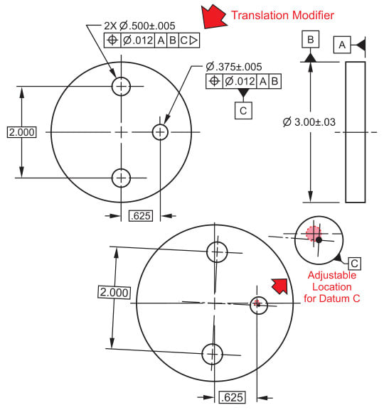
Here is another example regarding translation from my library, but the tertiary datum feature is a hole instead of a groove(slot).

2023-01-28_kbcah9.jpg


Season
 
SeasonLee,
This again means simply that the axis to axis distance in the fixture which includes the simulators for datums B and C is adjustable and not fixed at .625". Be warned that any suggestion to replace this specification by reversing the order between datum features B and C and using the customized datum reference frame will be a bad idea.
 
Burunduk,
Burunduk said:
.....Be warned that any suggestion to replace this specification by reversing the order between datum features B and C and using the customized datum reference frame will be a bad idea.......

I understand that mixing secondary and tertiary is a "bad idea", but could you, please, substantiate a little more. Why?
I am reading all the replies (Evan’s, 3DDave, pmarc, Seasonlee, yours) and I am not able to get a clear picture on why customized DRF, could not be used? Why is a “bad idea”? What is detrimental or could be detrimental?

I am not very well educated in this area (of translation modifier) so THANK YOU VERY MUCH for this interesting discussion.


SeasonLee,

I would say that your latest example is qualitatively similar to the one in the sketch I posted Jan 28 1:02 with showing the simulators with and without translation. I agree with Burunduk that the distance between the simulators B and C is adjustable.

I think I also agree with Burunduk that reversing the datum feature sequence and customizing the DRF would be a bad idea. Even though we saw a case earlier (plane-hole-slot) in which reversing the order and customizing could achieve the same result as the translation modifier, I'm not sure that this is possible for the plane-hole-hole case. But let's see what happens if we try it:

If we change the datum feature sequence we get |A|C|B|.
Writing out the implied DOF constraints, this would be | A[z,u,v] | C[x,y] | B[w] |
We want B to constrain the x and y translations, so we need to customize C. This would give us | A | C[] | B[x,y,w] |
We don't want B to constrain the w rotation, so we need to move w to C. This would give us | A | C[w] | B[x,y] |

I don't think that works, | A | C[w] | B[x,y] | isn't a valid customized DRF. The cylindrical simulator for C isn't capable of constraining w as a secondary datum feature.

It appears that in some cases a customized DRF can duplicate the effect of the translation modifier but this isn't generally true.

Evan Janeshewski

Axymetrix Quality Engineering Inc.
 
Not all transforms require reversal - separating translation from rotation controls appear to. So B's incomplete suggestion (how is he at a loss for words about the effect in this case?) that reversal would not work correctly is correct.

However, using: | A | B[x,y] | C[w] | does.

Edit:

A thought on this occurs to me - the translation modifier "moves" the (analog or digital) physical datum feature simulator while the customized datum reference frame moves the datum reference frame. It's because they are inverse operations to each other that the order of the datum references affected by them are reversed.

In this case there is no translation of the CSYS, so there is no effect from the inverse of an operation that doesn't happen.
 
3DDave,

The | A[z,u,v] | B[x,y] | C[w] | specification describes the same DOF constraints that would be present by default - it doesn't customize anything. Are you saying that | A | B | C | would mean the simulators are all at basic location but | A[z,u,v] | B[x,y] | C[w] | would mean that the C simulator is allowed to translate away from its basic location (and thus be equivalent to specifying the translation modifier) ?

Also, you lost me with the idea that moving the simulators and moving the DRF are inverse operations and affected by reverse order - I'm not able to see that at all. It may be because I'm still seeing the customized DRF as moving the simulators.

Evan Janeshewski

Axymetrix Quality Engineering Inc.
 
greenimi,
I think that Evan's explanation covered well the reasons that it is a bad idea to try to imitate the effect of the translation modifier in this particular case. My opinion is that it is generally true. The customized DRF has its uses, but sometimes attempting to reproduce the effect of the translation modifier with it requires reversal of datum reference order, such as was suggested by Evan for the plane-hole-slot case at 29 Jan 23 05:21 and later confirmed by 3DDave at 29 Jan 23 07:07. In that customized DRF, |A[z,u,v]|C[w]|B[x,y]| the tertiary datum reference constrains more degrees of freedom than the secondary and the secondary is the "clocking datum" which constrains the otherwise last rotational DOF. In addition to the fact that it is questionable whether doing so unfixes the basic mutual location between the simulators (I claim that it doesn't), such reversal goes against the general logic of datum precedence order and hierarchy, and I don't think it is justified by the design intent of letting the datum feature simulator for the slot be movable to be able to better engage with the tertiary (in the original scheme) datum feature and do its "clocking" job.
 
axym,

By default (except for 1994) the simulators for the two hole case are fixed in location and mutual orientation, meaning C controls both X and Y in parallel with B and the combination controls rotation. The 1994 interpretation that C doesn't control X and Y is based on problematic rules. The custom datum reference frame makes explicit the interpretation that the translation modifier rule is intended as a patch for.

The custom datum reference frame example explicitly only controls rotation. the second hole, C is evaluated as a point at (r, omega) and "r" is ignored. There is no translation.

In the case of the slotted part:

For the customized datum reference system the initial coordinate system Y origin would be established on the center plane of the slot, but that is dismissed and the coordinate system Y origin is moved vertically to align with the hole.

In the case of the translation modifier, the slot moves by rotation to be parallel to the X-axis and offset from the Y axis origin and the physical datum feature simulator translates to match it.

In the first case the coordinate system moves at the last step in one direction.
In the second case the physical datum feature simulator moves at the last step in the opposite direction.
 
Status
Not open for further replies.

Part and Inventory Search

Sponsor