Eng-Tips is the largest engineering community on the Internet

Intelligent Work Forums for Engineering Professionals

Customized DRF instead of a Translation Modifier 1

Status
Not open for further replies.

Burunduk

Mechanical
May 2, 2019
2,335
0
0
IL
During a recent discussion that developed in thread1103-501700 , claims were made that at every place where the Translation Modifier is used, the Customized Datum Reference Frame tool can be used instead.
Here is an excerpt of the argumentation:

3DDave said:
The point is that customized datum reference frames are a proper superset of which the translation modifier is a tiny part. That there is no function available via the translation modifier that is not contained within the customized datum reference frame capability. That the control of acceptable variation by the more capable approach is identical to the more limited approach with the correct syntax.

Other opinions that were expressed suggested otherwise:
Evan said:
In some cases (such as the plane-hole-slot case discussed earlier in the thread) the same DRF can be achieved using either tool but this is not true in the majority of cases.

I'm interested in clarifying the issue.
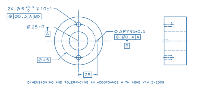
Below is a drawing example that uses the Translation Modifier tool.
The ⌀25H7 bore is the locating feature of this component in its functional assembly, and it also sets its initial orientation. It aligns to a mating shaft with a "sliding" clearance fit of H7/g6 (hole basis). The ⌀3P7 hole is intended to fit with a pin that will be assembled into it with an Interference fit of P7/h6 (shaft basis). The pin will contact a radial slot on the mating part to lock the rotation about the axis of the bore, to do the "clocking".
If you were to duplicate the effect of the Translation Modifier applied to datum feature B by using a Customized DRF, how would you go about it? What would the customized datum reference frame look like, and how would it override the default degrees of freedom constrained by datum features A primary, B secondary?
If you think this idea would not work and the translation modifier should be kept, please explain why.
I would appreciate everyone's opinions.
Thank you.

translation_mod._dwg._fzbed6.png
 
Replies continue below

Recommended for you

3DDave said:
If I didn't understand it the committee would not have made the changes according to it
Then, if you understand everything so well, maybe you can tell why the customized DRF, which is a concept that is clearly intended to be used to override degree of freedom constraints, should be used for purposes other than override degree of freedom constraints?

You are the one who decisively claimed in the other thread that the customized DRF can always be used instead of the translation modifier, without qualifying your statement that it will only be possible after you "prompt someone to change the standard". So it is still up to you to either support it based on the current content of the standard, or admit your mistake and say you will try not to make more misleading statements in the future.

3DDave said:
Datum symbols are attached to feature controls. Is that too advanced a concept?
That is not too advanced a concept, that is why it is used in my example. This is how datum hole B is designated. That doesn't make the control become the datum feature. That makes the feature which the control applies to be the datum feature.

You didn't answer the question.
How exactly, in the case of bidirectional tolerance of position, "the tangential control" can "be the datum feature"? What would attaching the symbol to the FCF of the tangential control change in terms of the datum feature/TGC/datum feature simulator compared to what is shown in my drawing, or compared to attaching it to the radial control, or directly to the outline of the datum feature? How is it "solving the problem" which the translation modifier deals with?

3DDave at 1 Feb 23 19:09 said:
More variation can be allowed in the radial direction and less, typically, in the tangential direction, which, if it was on the drawing, would allow the tangential control to be the datum feature solving the problem and accurately describing the use.
 
Since you cannot attack the claim you nitpick the language. Now that I have explained it and you clearly understand what I meant you repeat the language attack.

I've previously written that bi-directional tolerancing resolves the problem for practical mechanisms. Look at Tec Ease to see if they did an example of how that works. They do have some great cartoon depictions for beginners to follow.

Now, since you are using a pin, why did you fail to use a projected tolerance? Same reason you don't want to admit that you don't understand that a fit with a slot isn't a diametral fit.
 
Perhaps this will help out:
bidirectional_wks0pe.png


Does the word "unconstrained" make any impression? This same figure should also be in the 2019 release of Y14.5.1, which you should have a copy of. I had the crappy draft copy with many of the words blacked out by the "watermark," so I didn't get the released version.
 
The figure you now provided further reinforces my suspicion that it is not only a language issue that you are having, it is confusion between the processes of controlling a feature and using it as a datum feature. The "unconstrained" elements in this figure are virtual condition gages for the position controls of the hole, not datum feature simulators. Had this hole been labeled as datum feature D and referenced for some other control as a secondary datum feature (either at MMB or RMB) after C primary, the datum feature simulator for datum D (either fixed size or adjustable) would still be required to be stationary at the basic distance of 20 from simulated datum C. That would be the case regardless of which feature control frame the datum feature symbol D is attached to, or if it is placed directly on the hole outline. The only way to unlock that basic location of the D simulator would be using the translation modifier. Look at Dean Odell's YouTube playlist, maybe he has a demonstration of datum simulation principles that you can relate to more easily and learn from.

The projected tolerance zone is beside the point of the example I made to aid you to overcome the confusion between the customized DRF and translation modifier functions.
But I will address it anyway:
As you gain enough experience, you will realize that it is not mandatory to use the projected modifier in every single case where a hole for a stud pin or a screw is controlled by a tolerance of position. If the projection to depth ratio is small enough, the reduction of clearance that occurs due to the orientation error is not significant enough to require the use of the projected tolerance zone modifier.
In other cases, compensation for the inclination allowance can be applied when deciding the size of the clearance hole on the mating part, as long as the clocking alignment requirements allow this. See appendix B in Y14.5 for more information.
Also note that the face normal to the holes (from which the projection length would be defined) is not even used as a datum feature, so it is anyway different from the textbook examples that you are used to.
 
As I wrote, without an example of a picture from TecEase you would have considerable trouble and there, in the face of Y14.5.1, you still have trouble.
 
I do have trouble, in getting through your misconceptions.
The bidirectional tolerance of position separates the location control to two different directions of dislocation controlled by different tolerance values. In the figure, it unconstrains the location of each of the 2 virtual condition gages in the uncontrolled direction for each control. This correlates to two parallel-plane type tolerance zones for the resolved geometry interpretation, that combine into a cuboid tolerance zone limiting the axis of the actual hole around the true position.
As I tried to explain, this has nothing to do with the requirements of datum simulation when the hole is used as a datum feature, therefore it doesn't "solve the problem" (as you claimed) which the translation modifier deals with.

If this doesn't help, ask an experienced co-worker that understands Y14.5, and fixtures and gages, to explain to you the difference in the function of a fixture element to simulate a datum and the virtual condition gages for a bidirectional tolerance of position evaluation.
 
The center plane of the WIDTH of the hole is the datum. It defines a plane that is basically oriented to the higher level datums.

I realize why you like Tec Ease so much. Don Day, having passed away, presents no risk of contradicting you.

How will you keep that pin in the groove without it protruding an infinite amount or possibly running into the uncontrolled face of the part in the case where the pin is so short. As soon as you define where that face is you have a basis for the projected tolerance zone. Your lack of design skill should be of concern. Perhaps there is a book on machine design you could run off and read?
 
Unless otherwise specified, the true geometric counterpart and datum feature simulator is of the inverse shape of the datum feature. For a hole, the datum feature simulator is a cylinder and the datum is an axis. A bidirectional position tolerance doesn't change that. In figure 10-30 of Y14.5-2018, the bidirectional position control defines a 0.04 width of a ring shaped tolerance zone. Had a datum feature symbol C been attached to the 0.04 position tolerance FCF, and a different tolerance of position for some other feature would reference A,D,C - what would be the shape of datum feature simulator C, and what would be datum C? According to your logic, it would not be a datum axis. So what would datum C be, would the rotation about datum D be constrained by datum feature simulator C, and how would it differ from a case where the datum feature symbol C is attached to the 0.2 position FCF or the 0.04 perpendicularity FCF?

3DDave said:
How will you keep that pin in the groove without it protruding an infinite amount or possibly running into the uncontrolled face of the part in the case where the pin is so short

The amount of protrusion of the pin depends on the depth of the hole and the length of the pin. It's not affected in any way by how the position tolerance is defined, and by the presence or absence of the projected tolerance zone modifier.
The "uncontrolled face" could be controlled by perpendicularity to the central bore. Again, not your typical textbook example. This could be due to the fact that the face is kept clear from the mating part with the slot in it, and that mating part could be constrained by a shaft that mates in the large central bore. Again, the example's purpose was only to make a point about the function of the translation modifier, and it was not thought through for being used in an actual mechanism. Your attempt to provide an analysis of the design with only the partial information that was provided only reflects your inexperience.
Have you gone through a dimensioning and tolerancing training yet?
 
You had your chance to understand the difference in the purpose and function of the customized DRF and the translation modifier, it's a shame you didn't take that chance and only focused on off-topic distractions instead.

Right now, you also got a chance to understand how true geometric counterparts are determined from datum features and datum feature controls - an understanding you indicated to be lacking, but you don't seem to be willing to take that chance either. That's unfortunate.
 
What is the TGC of a width? Does anyone have a cartoon for you? You have already discounted any possible customized datum reference frame as being valid. Probably really hate the examples even existing in the standard.

What this means is that the committee needs to spoon feed the readers and cover every combination - make it like a picture-book menu. Then, if there is a situation they don't cover, it's not legal.
 
The TGC of a width is two parallel planes, which is not the case for a cylindrical hole, under any circumstances. The bidirectional tolerance doesn't change that. The diameter symbol is omitted from the tolerance value in FCF that controls displacement in each direction, but the controlled element for each tolerance of position is still the axis of a round hole, not the center plane of a width. Similarly, regardless of datum feature symbol placement, the TGC of a round hole is a cylinder.

I have no problem with the customized DRF concept or examples. They work fine and represent workable solutions. You're the one that claimed there is no practical application for it.
 
Status
Not open for further replies.
Back
Top