Continue to Site

Eng-Tips is the largest engineering community on the Internet

Intelligent Work Forums for Engineering Professionals

  • Congratulations KootK on being selected by the Eng-Tips community for having the most helpful posts in the forums last week. Way to Go!

Two-slider crank mechanism 9

To create faster and more economical internal combustion engines, I propose to use my invention - Riyanov double-slider crank mechanism (Two-slider crank mechanism). I received 4 patents in Russia (№ 2634851), China (№ 3349271), Japan (№ 6373516) and the UK (№ 3530879) for my invention, which can be used to create more environmentally friendly and faster engines, generators or in other projects.

SUBSTANCE: crank double-slider mechanism includes a crank, two connecting rods and two sliders. The second connecting rod is connected to the first slider at one end, and to the second slider at the other end. The second connecting rod length is equal to the sum of the double crank length and the distance between the connection point of the second connecting rod with the first slider in the initial phase of its movement measured in the direction of the first slider travel and the longitudinal axis of the second slider.
EFFECT: ensured full turn of the crank in one stroke of the extreme slider in the chain in one direction.

The unconditional effect of the two-slider crank mechanism is overcoming the limitation in the number of revolutions per minute in the internal combustion engine for the same working stroke of the slider, which can be used in internal combustion engines requiring high speed (for example, drones (land, air, water), subcompact cars, motorcycles), as well as in electric generators based on internal combustion engines, wave electric generators.

The key predicted effects are a gain in speed, a reduction in fuel consumption, the use of fuel with a lower octane number as a result of an increase in the working stroke of the slider, simplicity of design (gears are not used to double the speed).

I propose to use internal combustion engines based on the proposed mechanism primarily in unmanned aerial vehicles.

The subject of discussion is the possibility of practical application of the proposed mechanism in internal combustion engines.

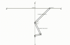
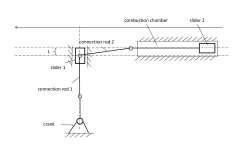
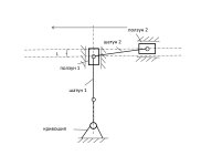
In existing internal combustion engines, the crankshaft makes half a revolution per stroke of the slider in one direction. In the proposed mechanism, it makes a full revolution per stroke of the outermost slider in the chain in one direction.Two-slider crank mechanism.jpgTwo-slider crank mechanism - animation.gif
 
Last edited:
How are the pistons linked while still having a pressure-tight combustion chamber to contain the combustion pressure?
 
How are the pistons linked while still having a pressure-tight combustion chamber to contain the combustion pressure?
The junction of the sliders is located outside the combustion chamber. Technically, this can be done using an element that is attached to the piston of the outermost slider in the chain and protrudes beyond the combustion chamber in the initial position (this slider is located horizontally in the diagram and moves in the combustion chamber). The second slider (located vertically in the diagram) ensures a full turn of the crank for a full stroke in one direction of the horizontal slider in the diagram. It can be made as a transmission link without a combustion chamber.
 
Along with all the obvious flaws and shortcomings I see the potential for the machine getting jammed or the horizontal slider reversing inadvertently when the crank is at BDC (horizontal slider at mid stroke).
 
Technically, this can be done using an element that is attached to the piston of the outermost slider in the chain and protrudes beyond the combustion chamber in the initial position (this slider is located horizontally in the diagram and moves in the combustion chamber)

Can you supply a picture of a way this can be done? If the piston is in the combustion cylinder and the outermost slider is outside, how does that happen?
 
Can you supply a picture of a way this can be done? If the piston is in the combustion cylinder and the outermost slider is outside, how does that happen?
In a simplified version, the pin is attached to the piston on the outside with one end, and is loosely connected to the connecting rod with the other. It sort of extends the piston beyond the combustion chamber.
 
Where does combustion take place? Anyway, with all the effort at patents there should be an idealized implementation showing how it would work with metal parts.
 
Where does combustion take place? Anyway, with all the effort at patents there should be an idealized implementation showing how it would work with metal parts.
The combustion chamber is connected to a slider, which is placed horizontally in the diagram. There are many ways to implement this mechanism. The novelty of the idea is patented taking into account the possibility of practical implementation.
 
If the combustion chamber is attached to the piston then the piston is seized and no work can take place.

If a simple diagram of how a practical device can be made is not possible then this is a dead end.

In the UK that isn't a valid patent number.
 
If the combustion chamber is attached to the piston then the piston is seized and no work can take place.

If a simple diagram of how a practical device can be made is not possible then this is a dead end.

In the UK that isn't a valid patent number.
This is a European patent validated in the UK. It is valid until December 2025. In a simplified version, the rod is attached at one end to the outside of the piston, so that in the initial position of the piston it extends beyond the combustion chamber, the other is freely connected to the connecting rod, which is also connected to the second slider (vertical in the diagram). I think I have already answered this question.
 
I went to the UK patent site. It says all issued patents start with GB or EN. If you can provide a copy of the patent that would be great. If you could provide a link to the patent at the UK patent site that would also work.

You have not shown a single example showing how this linkage could be built, so you have not answered the question.
 
 
Moving blocks around on a 2d animation is not the same as an engine design.
 
Thanks System Protection - it confirms a lack of implementation.

That was the link that should have been in the initial post along with a shaded image of a section of an engine using this mechanism.
 
So the link passes through the side of the combustion chamber?

Why is the ground connection labeled crank?

That is also not what was shown in the original mechanism as the slider 2 cannot move across the line of action of slider 1.

Come back with a working engine.
 
Take a look at the SAE papers by Jack Kentfield, for example paper 891866, where he goes into some detail of an over-center toggle linkage that provides extended expansion and all four strokes in a single crank rotation as well as potential VCR facility. It is a somewhat simpler mechanism than you have described.
 
Congratulations on your patents! It's a significant achievement.

Your concept might find good use in certain co-generation applications.

Whereas most engine designs look to bias the ratio of mechanical output to recoverable waste heat ratio towards mechanical output, your design looks very good for moving the ratio to favor recoverable waste heat.
 
So the link passes through the side of the combustion chamber?

Why is the ground connection labeled crank?

That is also not what was shown in the original mechanism as the slider 2 cannot move across the line of action of slider 1.

Come back with a working engine.
The connecting element passes inside the combustion chamber.
 
So the link passes through the side of the combustion chamber?

Why is the ground connection labeled crank?

That is also not what was shown in the original mechanism as the slider 2 cannot move across the line of action of slider 1.

Come back with a working engine.

Take a look at the SAE papers by Jack Kentfield, for example paper 891866, where he goes into some detail of an over-center toggle linkage that provides extended expansion and all four strokes in a single crank rotation as well as potential VCR facility. It is a somewhat simpler mechanism than you have described.
In the proposed invention, the idea concerns directly the transfer of translational motion into rotational motion. A twofold increase in the speed of revolutions per stroke of the outermost slider in the chain is achieved. Toothed transmissions are not used for this.
 

Part and Inventory Search

Sponsor