Eng-Tips is the largest engineering community on the Internet

Intelligent Work Forums for Engineering Professionals

un-referenced datums revisited

Status
Not open for further replies.

Tmoose

Mechanical
Apr 12, 2003
5,626
0
0
US
thread1103-439519

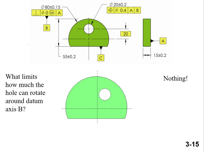
A couple of helpful images were included by Chez 311 in the thread above from 2018.

A did fairly extensive searching in ASME Y14.5-2018 for combinations of "datums", and "not referenced" but struck out.

Does anyone know where those images, or images like them, might have come from?

Also if non referenced datums are discussed in some version of ASME Y14.5 ?

thanks,

Dan T
 
 https://files.engineering.com/getfile.aspx?folder=59e6758d-b2fe-4310-8248-2369ec34b6ba&file=non_ref_datums_.PNG
Replies continue below

Recommended for you

I don't think I heard before about non referenced datum.
You might use them if a general note such as "Unless otherwise specified (UOS) all features are within profile|xxx|A|B|" is shown on your drawing.
 
Probably some instructional book for a course. AFAIK "not referenced" has never been discussed.

This seems more like would come from a training company that had instructors that HAVE HAD IT UP TO HERE with being shown examples of how companies and individuals believe it is supposed to work.
 
Agree, looks like illustration from textbook saying: "This is wrong and that is right"

Nothing else.

"For every expert there is an equal and opposite expert"
Arthur C. Clarke Profiles of the future

 
In looking at Y14.5-2018, the closest thing that I can find is in paragraph 6.3.2, where they mention (a couple of times) that a datum feature "requiring identification" shall be labeled etc.
So if a datum letter isn't utilized in a feature control frame (or a special note) then -- to me -- it doesn't "require identification" and thus it shouldn't be on the drawing.
I admit that might be a flimsy case, but oh well.
 
Here's a snip from the Tec-ease course. This was an actual argument I had with an inspector back around 2006 or so. He insisted that datum feature reference was implied if datum features were identified, even if they weren't in the datum reference frame. This is actually what the part looked like. Usually the question is "Why is the datum feature identified if it's not used in a datum reference frame?" The answer is "I don't know. That still doesn't mean its use is implied."

Screenshot_2023-12-29_095219_zm4kas.png


John Acosta, GDTP Senior Level
 
I agree with you John, but if the drawing is having a general note such as ""Unless otherwise specified (UOS) all features are within profile|xxx|A|B|" " THEN your answer "NOTHING" is probably not correct anyomore.
In the latter case, maybe the answer will be "SOMETHING".


For that Tec-ease snippet, couldn't you customize the datum reference frame, and use datum feature C only to control rotation?

So the callout could be something like A [x, u, v] | B [y, z] | C [w]?

That would appear to honor the intent of the position tolerance, and actually reference C appropriately.
 
As clever as that would be it makes more sense to use other methods. The complicated knots that are proposed in the standard as solutions for straight line problems is astonishing.

Simple task - show a manufactured mechanism, available for sale, with this dependency where the optimal and most permissive tolerance allocation is a diametral tolerance and demonstrate this property applies via a tolerance analysis.
 
greenimi said:
I agree with you John, but if the drawing is having a general note such as ""Unless otherwise specified (UOS) all features are within profile|xxx|A|B|" " THEN your answer "NOTHING" is probably not correct anyomore.
In the latter case, maybe the answer will be "SOMETHING".
But it doesn't have that note, nor did the original drawing, so the answer is still "NOTHING". Why even go down this road of trying to find something wrong with the lesson being conveyed?

ryanfeeley said:
For that Tec-ease snippet, couldn't you customize the datum reference frame, and use datum feature C only to control rotation?

So the callout could be something like A [x, u, v] | B [y, z] | C [w]?

First of all A could never constrain translation along x and B could never constrain translation along z even in a customized DRF, assuming x is horizontal in the main front view. Second, in the DRF in the drawing that I showed, all C could do is constrain rotation around z if it was tertiary and that's actually what's missing here.

John Acosta, GDTP Senior Level
 
u = rotation about x, v = rotation about y, w = rotation about z

x and u should not be together. Swap "u" with "w".

The Y14.5 committee needs to add a rule about combinations so that people can have more rules to memorize.

Better, they could use ax, ay,and az so errors like this are easily discovered. Or not. Math users typically use Greek letters for angles so there is no overlap in single character settings. α (alpha), β (beta), γ (gamma), δ (delta), and θ (theta)

If x was out of the page for the main face and y and z were in the main face, then the rest would be OK.
 
An academic argument could be made that a complex feature controlling all degrees of freedom with one released could have x and u as references - but that gets back to "show a manufactured mechanism, available for sale" where that is a reasonable control to make.
 
I saw many drawing with non referenced Datum this week!

They were from my own student...[banghead] I removed 10% on all those drawing... What am I doing wrong???

 
Status
Not open for further replies.
Back
Top