Continue to Site

Eng-Tips is the largest engineering community on the Internet

Intelligent Work Forums for Engineering Professionals

  • Congratulations waross on being selected by the Eng-Tips community for having the most helpful posts in the forums last week. Way to Go!

Uplift Transfer Loads? Can anyone please help me with this model issue? 1

Status
Not open for further replies.

May10May

Structural
Apr 27, 2020
9
AU
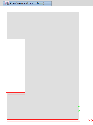
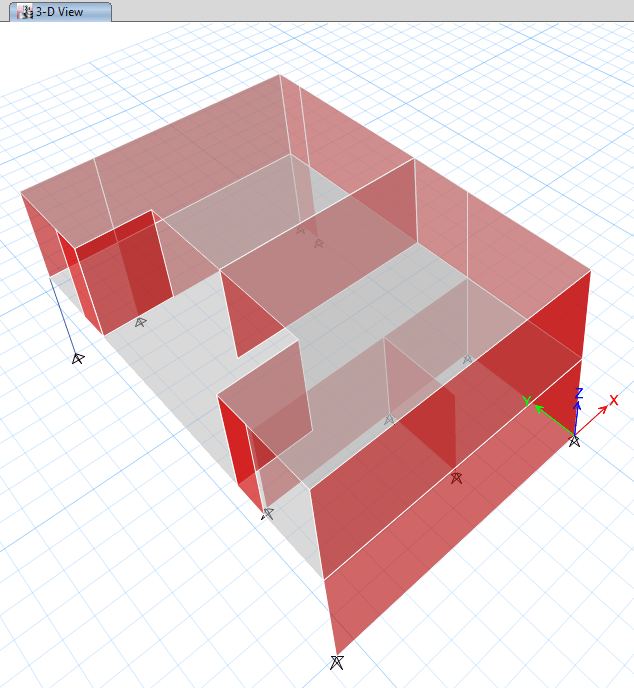
So I have simplified my model to make it easier to look. I am using ETABS for this building and use its export feature (loads above and floor) to SAFE to design the transfer slab on first floor.
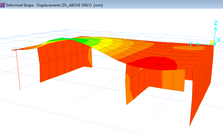
I then found this weird thing, though the internal transfer wall is in compression in ETABS, the left hand side node loads in SAFE are uplift and thus the deformation is uplift under transfer loads.

Can anyone please help explain what cause this? Is this normal? What do I need to do in ETABS before exporting floor and loads from above to SAFE for me to design this transfer slab? Thank you.
(I don't know how to upload models so I have uploaded pics as below, much appreciated if anyone can let me know how to upload model files too)

First Floor (Transfer Slab)
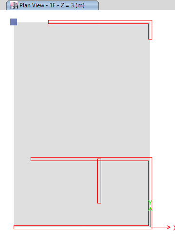
1F_vowztg.png


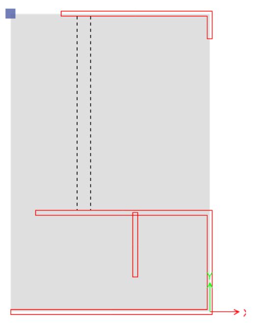
Second Floor
2F_gzmah8.png


3D
3_vspqrw.png


Deformation in SAFE
d_fnccdn.png
 
Replies continue below

Recommended for you

It looks like you have uplift due to lateral in-plan loads. the slab is seeing that load, so it needs to resist the load
 
Without having more information, here are two suggestions:
1. As suggested by Eric, the uplift is due to the wall above (long in the X direction, approximately at the centerline in the Y direction) resisting lateral loads in the X direction, and the associated overturning of that wall imposing uplift the larger span of your transfer slab.
2. Perhaps a cardinal direction error between SAFE and ETABS, where down-loads in one program are interpreted as up-loads in the other? I don't do much of this type of work and do not have familiarity with the programs, but it is a potential whenever importing/exporting data from one software package to another.
 
You have irregular arrangement of support (center of rigidity), and with an opening direct below, uplift is possible at the left upper corner.
 
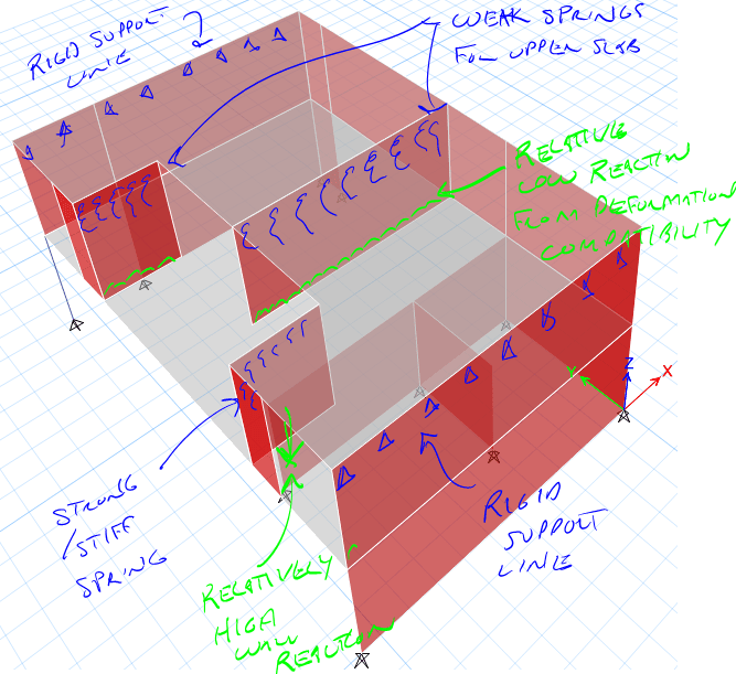
Because it is a 3d model the slab below the long wall in the middle is too soft so the upper slab acts more like a single span to the outer walls and the short walls near the lower supports. This puts more load in the first span and less in the long span which yields the uplift.

see this thread:
My Personal Open Source Structural Applications:

Open Source Structural GitHub Group:
 
Thanks for your input guys.
No, there is no lateral loads assigned. Just dead load and live load.
 
This makes sense. So if the layout cannot be changed, what should I do in Etabs before exporting to SAFE to make the transfer loads 'normal'? ( I don't think I can use the above 'weird' loads to design the slab directly, can I?) I have tried to revise the stiffness of walls but doesn't make much difference.
 
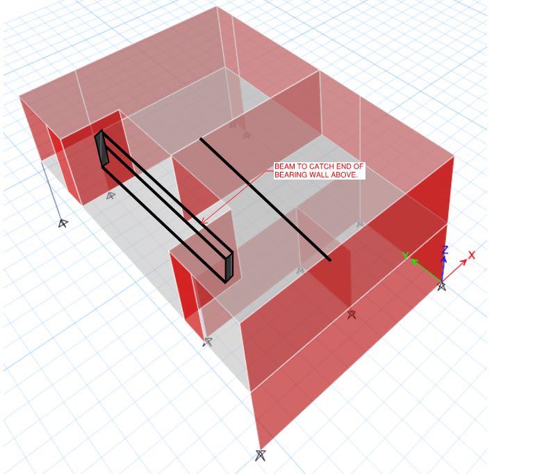
First, let's celebrate your model. It's revealed some accurate and vital information to you: the original structural scheme for this building is lacking. Were it possible to do so, I feel that the simplest path for rectifying the situation would be adding the beam that I show below. I recognize you're desire to maintain the original layout, however, so I'll not belabor the "back it up and make it better" option. Rather, I'll answer your specific question about how to adapt you model. Keep in mind, however, that both approached that I recommend will wind accomplishing the same thing: providing stiffness that the beam below would do a better job of providing.

c01_wuxsiu.jpg
 
Model Fix #1

1) Model the upper floor by itself and record the reactions at the bottom of the walls.

2) Model the lower floor by itself and load it with the wall loads from #1. When you do this, be sure to adjust your slab proportions such that reasonable transfer slab deflection limits are enforced. Limits to the tune of the lesser of 1" max anywhere or L/400 at a minimum. Enforce these limits on long term deflections that account for creep and concrete cracking.

Model Fix #2

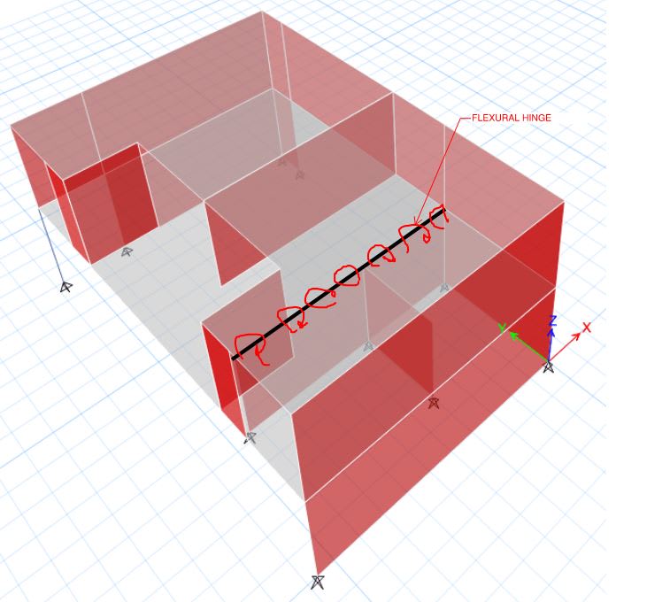
3) Model a flexural hinge in your slab where I've shown it below.

4) Design your slab in SAFE being sure to adjust your slab proportions such that reasonable transfer slab deflection limits are enforced. Limits to the tune of the lesser of 1" max anywhere or L/400 at a minimum. Enforce these limits on long term deflections that account for creep and concrete cracking.

5) Come back and put some nominal crack control reinforcing over top of he wall where we assigned the flexural hinge.

c02_seubwt.jpg
 
Thanks KootK. I wonder what location is this beam going to be? because looks like you are connecting the beam to walls above not below. (I reckon you thought these two walls were at lower level and arrange a beam to pick up the middle wall above?)

1) Model the upper floor by itself and record the reactions at the bottom of the walls. said:
Model the lower floor by itself and load it with the wall loads from #1.
May I kindly ask what the purpose is of doing this? by modelling it separately we are treating the transfer slab to be infinitely stiff, which is unrealistic and transferred loads will be increased greatly. Won't it be more realistic if I export the loads above from ETABS full structure model? In another word, what is the problem of directly exporting floor and loads from ETABS to SAFE? (I can set the modify the stiffness of walls to consider crack if necessary). Can you please elaborate on this? I have seen this Link from other thread about the similar topic.

Model the flexural hinge if ETABS? may I ask why place a hinge here to let it crack considering the moment in slab is not much at this area?

All in all, what happens if I don't make amendment but simply export to SAFE?

Sorry too many questions but I really want to figure out and thank you again.
Cheers


May10May said:
..(I can set the modify the stiffness of walls to consider crack if necessary)..
The Stiffness of the walls won't really make a difference the "issue" is the stiffness of the transfer slab supporting the walls.

By modeling the top floor separately and getting reactions to then apply as load to the transfer slab you are landing somewhere between the tributary area method and the 3d elastic analysis noted in your link. If you then design the slab as KootK noted and limit deflections you can back into stiffness modifiers to apply to the transfer slab in the full 3d model which can help get you closer to the behavior you were initially expecting.

Because concrete deflection are so variable and our calculations are really just best guess approximations its usually recommended the envelope these types of designs.

My Personal Open Source Structural Applications:

Open Source Structural GitHub Group:
 
OP said:
because looks like you are connecting the beam to walls above not below.

The beam is meant to be connected to the walls below. The beam would be integral with the the second floor slab. as shown below.

c01_nwteqq.jpg


OP said:
by modelling it separately we are treating the transfer slab to be infinitely stiff, which is unrealistic and transferred loads will be increased greatly. Won't it be more realistic if I export the loads above from ETABS full structure model?
.

1) Unless you've done some advanced stuff with staged construction modelling, you full 3D model is also in accurate. It assumes that all of your suspended slabs, beams, and walls remain shored until the entire structure is completed. Then your live and environmental loads are applied to that structure still with the shoring in place. Then you remove the shoring and start to let things deform. Obviously, this story not 100% accurate ether.

2) The goal for all of these strategies is produce a very stiff slab within practical economic limits. That is the parameter which will usually produce conventional detailing and problem free in service performance. As such, coming up with a nice stiff slab is one answer to the problem you brought to us: getting rid of the uplift and having normal concrete detailing. One strategy that you could use to adjust your model is to simply take your 3D model and keep adjusting the thickness of the long span floor slab until the idiosyncrasies disappear. That'll work but it's not the approach that I'd use. To my knowledge, ETABS isn't great for detailed estimates of long term concrete slab deflections. And, as celt83 mentioned, those estimates are critical to your success in this. Some problems that your full 3D model may be causing include:

a) Many of your second floor slabs may be hanging, heavily, from the walls above rather than supporting them. That condition, at the joints, can be difficult to detail reliably.

b) Because of (a), you may be dragging loads around through the roof slab to strange places in plan which are contributing to your strange results.

c) If your second floor spanning elements will not be shored when your second floor walls and roof are cast, you may be missing important construction loads on your second floor.

OP said:
May I kindly ask what the purpose is of doing this?

3) The purpose, when combined with appropriate deflection design, is to encourage you to provide the stiffness mentioned in (2).

OP said:
In another word, what is the problem of directly exporting floor and loads from ETABS to SAFE? (I can set the modify the stiffness of walls to consider crack if necessary

4) So far, this process has not encouraged you to provide the stiffness mentioned in (2). Also see (1).

OP said:
Model the flexural hinge if ETABS? may I ask why place a hinge here to let it crack considering the moment in slab is not much at this area?

5) The purpose, when combined with appropriate deflection design, is to encourage you to provide the stiffness mentioned in (2): a stiffer slab over the long span.

6) said:
All in all, what happens if I don't make amendment but simply export to SAFE?

6) Then nothing has changed and you continue to have the modelling and rebar detailing idiosyncrasies that brought you here in the first place. If you're happy with the assumptions that your modeling approach implies and you're happy with the deflections and unconventional detailing that your design will produce... then you have no problem and you can simply continue to prosecute your original design.
 
Unless you start adding a beam as suggested by Koot, your 3D analysis is more appropriate IMO. In SAFE, it will be difficult to capture the 3D reality of how this will behave in the real world unless you go back and forth between the SAFE/ETABS model to add the springs as suggested by Celt.

I opened your model and I do not see any section modifiers for the bending stiffness. I assume this will be conventionally reinforced. You need to look at the deformation of the structure carefully to ensure an appropriate design. How much the 2nd floor deforms may have a significant impact on the design of the 3rd.

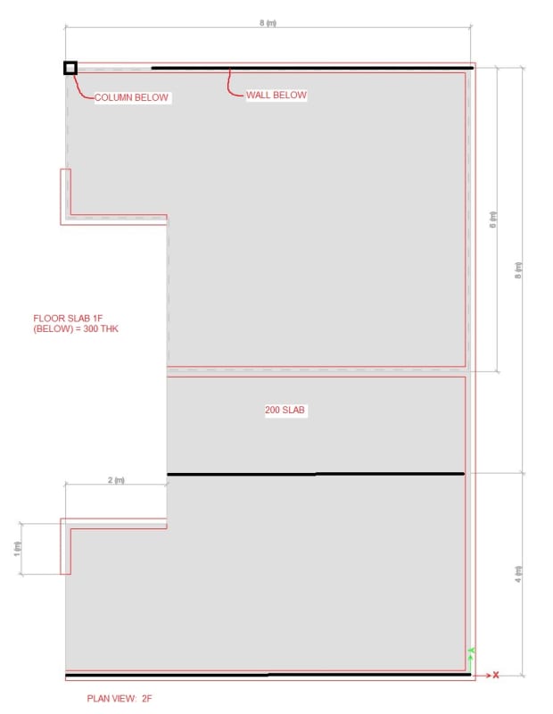
Below is a plan view sketch of the span arrangement for others: dimensions in meters
eng-tip_ngwwqd.jpg
 
Brad805 said:
Unless you start adding a beam as suggested by Koot, your 3D analysis is more appropriate IMO.

The gist of my approach was meant to be that you'd ultimately beef up the slab to achieve similar stiffness provided by the beam even if it were omitted. In my mind, a stiff transfer structure is the key a) successful performance b) conventional detailing and c) the use of simplified methods. With a flexible transfer slab, I agree, the 3D effects need more detail than simplified methods are likely to provide.
 
You can do a "staged construction" analysis in ETABS. This should get the correct loads onto the transfer slab for when you export into SAFE. If you haven't done this your loads are incorrect, as explained by other people above.
 
Thank you very much everyone for your full explanation. Appreciate that. I think I am getting the ideal.
So does the following method sound reasonable?
1. Add Sequential Construction Case (dead load included only) in Etabs, lets name it 'Real_DL'.
2. Run Etabs and export the 'Real_DL' above and normal live load 'LL' above (together with load combs) to SAFE.
3. Define load cases for long term deflection to consider crack & shrinkage etc. These cases associate with 'Real_DL' load pattern instead of ‘DL' for full 'shored' model.

Question here is, what about the live load? I didn't include the live load when defining sequential construction case in ETABS because I think it is reasonable to say live load applies only after the whole structure is completed. But if I don't include it in, the live load will also cause the initial problem - truss action in transfer slab and lead to uplift transfer loads being applied to transfer slab in my SAFE model. What's your thought on this? Thank you.
 
OP said:
But if I don't include it in, the live load will also cause the initial problem.

Your fundamental problem here isn't your analysis method. Rather, it is a lack of stiffness in your transfer level as I described previously. That is what needs fixing.

I recommend fixing the stiffness deficiency using one of the simple methods that I described earlier. In my book, using a 3D sequential construction analysis on a two story building lies somewhere between overkill and an abuse of computing power.

Focus on improving the actual structure rather than just improving the model.
 
I second KtooK's point of view. Your model need to be modified. But I do agree that you shall check dead load case alone, to see whether the uplift tendency exists (reaction too small). Was the uplift caused by pattern load case?
 
Status
Not open for further replies.

Part and Inventory Search

Sponsor

Top