Continue to Site

Eng-Tips is the largest engineering community on the Internet

Intelligent Work Forums for Engineering Professionals

  • Congratulations waross on being selected by the Eng-Tips community for having the most helpful posts in the forums last week. Way to Go!

Uplift Transfer Loads? Can anyone please help me with this model issue? 1

Status
Not open for further replies.

May10May

Structural
Apr 27, 2020
9
AU
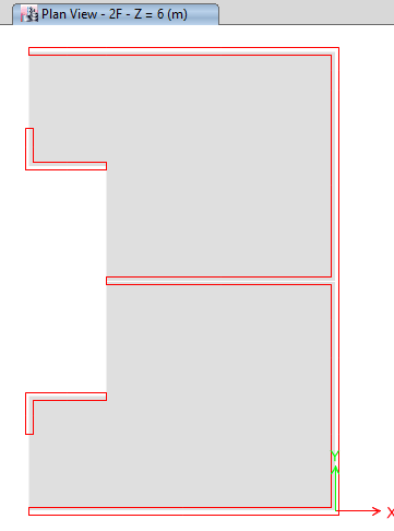
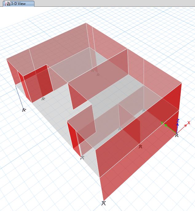
So I have simplified my model to make it easier to look. I am using ETABS for this building and use its export feature (loads above and floor) to SAFE to design the transfer slab on first floor.
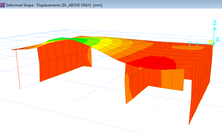
I then found this weird thing, though the internal transfer wall is in compression in ETABS, the left hand side node loads in SAFE are uplift and thus the deformation is uplift under transfer loads.

Can anyone please help explain what cause this? Is this normal? What do I need to do in ETABS before exporting floor and loads from above to SAFE for me to design this transfer slab? Thank you.
(I don't know how to upload models so I have uploaded pics as below, much appreciated if anyone can let me know how to upload model files too)

First Floor (Transfer Slab)
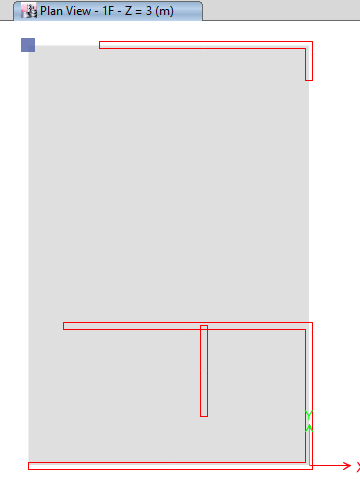
1F_vowztg.png


Second Floor
2F_gzmah8.png


3D
3_vspqrw.png


Deformation in SAFE
d_fnccdn.png
 
Replies continue below

Recommended for you

I don’t understand how the model can be correct if the longest most heavily loaded span is rising.
 
I get that the transfer slab is too soft and I am trying to re-check its deflection when taking construction sequences into consideration to see how thick it has to be to make the deflection reasonable small.
The model is actually more than 2 stories, like I said it is a simplified model. And the beam you mentioned above cannot be arranged because there are floor-to-ceiling windows under. I understand the isolated floor method you suggest but as Retrograde has mentioned the sequential construction case in ETABS so I am wondering what the standard method will be if I follow this method?
 
I am modifying the model by increasing the thickness of the slab.
Sorry I dont get the question here, I think the uplift is caused by the truss action in the full model.

 
May10May,

I share Tomfh's concern, that the deformed shape does not make sense. Without lateral load effects, where is the lift force coming from? Please double check your model and loading cases.

Also, except the end walls, I thing rest of the walls should be considered non-structural elements, and be left out of the model. So the load would be more evenly distributed to the supports.
 
Tomfh said:
I don’t understand how the model can be correct if the longest most heavily loaded span is rising.

The apparent "rising" might happen if your DL is applied in the positive upward direction.
 
JLNJ,

Can you elaborate your explanation further - when is the occasion to apply the DL in upward direction? Just curious about it.
 
retired13 said:
when is the occasion to apply the DL in upward direction?

RISA3D lets you define gravity in any direction. Normally you make the positive Y-axis your vertical, but it doesn't have to be that way. So if you make positive Y "up" you need to assign -1 to your self-weight to make sure it pushes in the downward (-Y) direction.
 
OP said:
I get that the transfer slab is too soft and I am trying to re-check its deflection when taking construction sequences into consideration to see how thick it has to be to make the deflection reasonable small.
.

If you're committed to the 3D modelling approach, I feel that this will wind up being an iterative process regardless of whether you consider construction sequencing or not. To solve your original problem of the strange uplift, corrections will need to be made to your ETABS model so that the forces that get exported to SAFE make sense to you. However, to my knowledge, ETABS is not as great for long term concrete deflections as SAFE is. So I see the process unfolding something like this:

1) Stiffen the slab (or whatever you think needs stiffening) in the 3D ETABS model until you stop seeing the goofy uplift condition.

2) Export the transfer slab to SAFE and investigate its stiffness in greater detail.

3) Based on your SAFE investigation, refine the thickness and stiffness of the transfer slab in ETABS and re-export the loads to SAFE as required.

4) Return to #1 and rinse and repeat until you close on a design that eliminates the weird uplift and that you feel is satisfactorily efficient.

OP said:
I understand the isolated floor method you suggest but as Retrograde has mentioned the sequential construction case in ETABS so I am wondering what the standard method will be if I follow this method?

I'm aware of the sequential construction business. I was actually the first in this thread to table that concept. That said, I brought it up to highlight potential inaccuracies in your previous 3D model. I never though that you'd actually latch onto the method as your way forward.

OP said:
The model is actually more than 2 stories, like I said it is a simplified model.

Can you share with us the real number of stories of this building? Maybe a screenshot of the overall ETABS model? Simplifying questions here is a good strategy for keeping responses focused. That said, in some instances, it's just much easier for respondents to offer quality advice if they understand the big picture. I feel that this may well be one of those cases now.

Staged construction modelling has long been the domain of very large / very complex structures. Unless your structure is a lot larger than two stories, I still question whether staged construction is appropriate. And a structure large enough to justify sequenced construction modelling almost certainly isn't going to work with such an in efficient transfer structure at the bottom. That said, if you already own the rights to the tools needed to do such an analysis, and are confident that you can execute it with the appropriate skill, it costs you very little to play around with construction sequencing and see how it affects things. Based on what you've said above, however, I don't get the impression that it is lack of consideration for construction sequencing that is causing your uplift issue.
 
OP said:
And the beam you mentioned above cannot be arranged because there are floor-to-ceiling windows under.

I understand. Most of our projects involve client goals that are not related to structure and for which we are obligated to help our client realize to the best of our abilities. That said, an architect's or owner's goals don't supplant the laws of physics. If you're going to fix the goofy uplift problem, you've probably got to change something about the structure, not just the model. There are infinite ways to change the structure but, given what you've shown us so far, one of the most direct and efficient ways will be to add stiffness to whatever supports that central, second floor bearing wall. Some options for that include:

1) The beam that I suggested.

2) Thickening the slab.

3) Perhaps prestressing the slab.

But all of these solutions are really just permutations of the same, single solution: adding transfer structure stiffness where it would be the most efficient to do so.
 
JLNJ,

Thanks. If I understand correctly, it indicates an input mistake.
 
retired13 said:
Thanks. If I understand correctly, it indicates an input mistake.

It’s a mistake that gets made with gravity loads. Some programs model gravity positive downwards, and some positive upwards. Someone I knew worked on a case as an expert witness where gravity was modelled upside down. The structure misperformed quite badly when gravity corrected the error.
 
Yeah, I like program to use right-hand-rules in determining positive, negative force and moment directions. Otherwise, the so called "mental mistake" occurs. But the graphic output of deflections/stress diagrams shall alert an experienced user though.
 
Status
Not open for further replies.

Part and Inventory Search

Sponsor

Top