Eng-Tips is the largest engineering community on the Internet

Intelligent Work Forums for Engineering Professionals

Very basic beam problem 1

Status
Not open for further replies.

EsoEng

Mechanical
Mar 8, 2008
20
0
0
GB
I am embarrassed to be posting this and asking for your help. I should know the answer. However, my knowledge is rusty, and my confidence shot.

The problem: what is the maximum stress acting on each of the two bolts, as labelled in the diagram? (A third, lower, bolt connects the upper arm to the spacer, and the spacer to the vertical plate, below the two main bolts. It does not pass through the entire assembly as the other two bolts do, and it is repeated on the other side.)

Hitch_with_labels_hlvzir.jpg


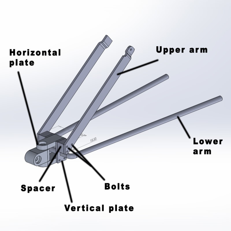
I am designing a trailer hitch for a motorcycle. When analysing stress in the bolt, I am wondering how best to go about it. The bolt passes through the upper arm, the spacer, the vertical plate, and the horizontal plate, and then passes through the opposing vertical plate, spacer and upper arm, as illustrated in the above diagram. The load originates, for the purposes of this analysis, at the horizontal plate. The bolt is, therefore, enclosed within all of these respective components, which restrict its bending.

For the analysis, should the force be applied in the centre of the bolt (beam) representing the horizontal plate, and the remaining length, on either side, constrained? Or, should the spacers and vertical plates be neglected so that only the ends of the bolt where they attach to the upper arms be constrained?

I have been using FEA software that is new to me, and which I am yet to be confident in. It is giving me a wide range of values depending on how I constrain the bolt. The basic manual/traditional formula I used is

stress = (moment * radius of bolt) / I

My calculation was only in acceptable agreement with my FEA analyses when I constrained the entire bolt other than the length of its centre, where it mates with the horizontal plate and where the force was applied. When the model was constrained differently, such as only where the bolt mates with the upper arms, FEA predicted significantly less stress, which, to me, is counter-intuitive.

I really would be grateful for a little guidance on this, to restart my brain. Thanks.
 
Replies continue below

Recommended for you

Do not use FEA to analyze the bolts. Just use a simple beam type FE model to get the forces in each arm, plate, etc. Then with those forces draw a free body diagram of each bolt. There are multiple shear planes on the bolts to check first. Then maybe check bending in the bolts, but frankly bolts should not be so skinny that they are critical in bending. And check bearing stresses in the arms and plates.
 
whilst I don't disagree, and I remember something like this in the past (maybe in the student forum) I think we need to understand the design limitations (and the manufacturing available) before we say "yech".

you are I think solving some design issues at the expense of others, and maybe don't realise this (or maybe don't want to make a long and rambling 1st post).

some things I see with your design.
1) you have the hitch eye free to rotate laterally. Whilst this may prevent the trailer from "wagging" the bike (paraphrasing the saying the tail wags the dog) you have to think about this more. if the trailer is free to move side-to-side how will that work out ? It may be something you evaluate under testing, but that's pretty late in the process. Have a plan B ... if the trailer motion with a free hitch is unacceptable, what'll you do ? what do people do today with this ? (maybe your design is typical, IDK)
2) the lateral stiffness of the frame is pretty "awful", how does it react to lateral loads ?? You are of course very limited in what you can do for this ... lateral loads will bend the frame.

What are typical motor cycles trailers like today ? If not like this, then think hard about the differences.

Are you working in a team, and is it your part to do the structural analysis ? (rather than the overall design) you seem to be fixated on this. This is a very simple frame and should be easily solvable to hand. At least do the static analysis by hand, and maybe some of the dynamic analysis with FEM. If doing FEM, how are you coming up with loads ? Assuming the trailer applies a load to the hitch, and seeing what this does to the frame ?? How realistic are these loads ? How do the dynamics of the trailer affect the bike ? The static loads should be very small ... the bulk of the trailer load goes down the trailer wheels, the hitch should see only something like 5-10% of the trailer load. I imagine big load cases are when one of the trailer wheels "stops" (hits a rock or something, generating a large braking force).

Pay attention to how the arms attach to the bike. Bikes have large pieces which are sprung and if you're attaching across one of these spring connections, then you're in for trouble. Make sure the trailer is attaching to a common lump of bike.

But to respond to your question, your bolts are working mostly in shear (which is easy to analyze for, since bolts are shear allowables). Your spacers put a large amount of bending into the bolts which would normally reduce their shear capacity. I would suggest bending the upper arms and dropping the spacers. But you may have very limited bending capability, and want to use simple flat arms; ok, but these are the design compromises I mentioned at the beginning. And all 3 of your bolts are carrying load into the upper arm, not just the lower one (unless of course you had the pope come round and make an infallible decision about this).

"Hoffen wir mal, dass alles gut geht !"
General Paulus, Nov 1942, outside Stalingrad after the launch of Operation Uranus.
 
@SWComposites, thanks. I have drawn FE diagrams, but have a confidence issue concerning how to define loads and constraints, as described in the OP. It is the interaction of the other bolts, and components the bolts pass through, that confuses me.


@MintJulep, I am open to criticism, and even that I should start again. The design shown is not complete. There will be an additional member linking the upper arms for lateral stiffness, and the lower arms will connect to pannier racks for further stiffness. The unlabelled rear-most component, the coupler, has been redesigned already so that it splits to allow easier/quicker trailer coupling. However, it is somewhat inelegant in that half would remain, but it would be secured by a storage strap when not coupled with a trailer. Overall, the design is a compromise based on stock material sizes, and available tools (budget) to actually make the thing, and also minimising weight.

My main concern is the strength of the design. If it is strong, and if it is not too heavy, and of course if it provides the desired function, then this is all I am really concerned with. Future refinement is another matter. What is it about the design that makes it awful, and could you make any suggestions for alteration, please?


rb1957, thanks. I did limit the OP, yes. As I described in my reply, immediately above, to MintJulep, the design shown is not complete, and will feature other elements that will increase its lateral stiffness. Working within the envelope afforded by a motorcycle is, of course, limiting.

The hitch, and together with the trailer, facilitates 3-axes of movement. The trailer needs to be as free to move as possibly to prevent destabilising the motorcycle - and causing a crash. Also, it will be used off-road, so range of motion is critical. And that is where the loading is focused - as you described, a sudden braking scenario when the trailer is caught on something.

I'm working alone. The design is the concept based on available motorcycle attachment points, desired range of trailer motion, and strength. I am in the design evaluation stage, and desperately trying to regain a grasp of understanding loading (hence this thread). It's been ten years since I was in a classroom with this stuff, and I have done very little since leaving that classroom.

Thus far, the bolt in question is under a maximum loading stress of ~1000 MPa, which is far too high (this is a worst case scenario within the design, so an unusual loading situation. Under normal operation, the loading is very low, but my focus is on worst case scenario). However, in FEA, values ranging from ~140 - ~1400 MPa are calculated, so you can see why my confidence is shot. It's apparent that I do not know what's going on, and that my lack of awareness is mostly in the new FEA software I'm using, but also as described in the OP.

The shear forces acting on the bolt are not a problem, and I would have thought that the way the bolt is enclosed the bending would be minimal. Where you say the spacers add bending, I presume you mean the added length rather than the component itself? As I just wrote, I would have thought the enclosure of the spacer prevents bending thus reducing bending stress. Bending the upper arms is a good idea, which I will strongly consider. They are already bent at the top to allow mating with an attachment point above the rear wheel - bent so that they attach while allowing room for the wheel itself.


Ok, I understand you limited your post to direct our attention, but that ain't gonna work ! posting a partial frame (and not clearly saying so) raises all the questions you got.

Don't really understand your FEM results "values ranging from ~140 - ~1400 MPa" ... the bolts will be all over the place, some heavily loaded, some lightly.

You're to be congratulated in questioning your FEM results, but this structure really doesn't need FEM; just work through the loadpaths (Free Body Diagrams, look them up if you need to refresh).

The load on the hitch is reacted by the two "horizontal" plates via the bolt. Work through a loadcase or two and show us how you think it'll work.

You can also develop the loads in the frame, axial loads in each ... vertical loads in the upper arms (which induces load in the lower arms), braking loads in the lower arms.

You'll need to do a FBD of the trailer to get good loads at the hitch. You can do all this loadpath "stuff" with sample loads (1000N vertical, 1000N braking) to get a feel for things, then combine and scale to suit your actual loads.

As suggested above, modelling bolts in FEM is somewhere between dangerous to misleading to wrong. The tools these fays make it far too easy to get misled. Sure the s/ware salesmen show you all the neat ways the FEM can model the real world, but you need a lot of understanding of the real world and FEM before you can reliably use them. Either hit the books (Strength of Materials) or maybe visit a nearby uni or college or maybe a nearby engineer. Or "wing it" ... if it looks stout enough then maybe it is !?

bolts and spacers ... bolts normally clamp things together, transferring load immediately into the next member. We analyze bolts by (initially) saying the reactions are at mid thickness and the bolt bears evenly over the thickness. This is a typical conservative assumption (conservative for the bolt that is). As the shear on the bolt increases the bearing becomes more triangular with the load getting closer to the parting plane, in the ultimate case the shear is at the parting plane and bolt bending is "minimal", and you get the published bolt shear allowable. Look this up if you want a longer story. With spacers the bolt is no longer carrying load immediately into the next member, so in the ultimate case there is a large offset between the applied load (from the hitch) and the reaction (into the frame). Thus the bolt (and yes part of the spacer too) are in bending. The simple approach is to have the bolt bending and the bolt shear combined, discounting the bolt shear allowable. A much more complicated analysis would have the spacer involved, depending on the load preload, but seriously this is a very complex analysis, you'd be better off testing this ... a simple enough test ... I'd start with a single bolt through five elements (the central loading member, two spacers, and two reacting members/plates). Yes, you can say the bolt will bear against the hole wall, if it is very tight tolerance, that may not suit the rest of the design, up to you. But creating an analysis for this is very complex, and testing is much easier.

What design elements do you have to control the trailer's lateral movements, swinging around the hitch pin ? This requires so detailed design thought.

Why have a single bent lower arm ? and not two lower arms bolted to the hitch (like the upper arms) ?
Why have two upper arms, instead of a single bent arm (like the lower arms) ?
And the answer could be "I don't think I can bend both the upper and lower arms and get consistent matching bends".
Are you welding the lower arms to the vertical plates ?

"Hoffen wir mal, dass alles gut geht !"
General Paulus, Nov 1942, outside Stalingrad after the launch of Operation Uranus.
 
@rb1957, thanks again. I appreciate you taking the time.

The lower arm design is inspired by a similar motorcycle tow bar design I found during background research. It is welded to the vertical plates. The upper arms are flat bars because they need to fit in-between the motorcycle twin mufflers to reach the upper mounting points while clearing the rear wheel - there is insufficient space for a tubular design. Ultimately, the design will meet the worst predicted stress case either method predicts, but I'd prefer to keep the design minimal (in terms of weight and components), and, primarily, have a good understanding of what is going on. It would be good to test empirically, I agree, but I'd prefer to only need to manufacture once, so am relying on the theoretical process.

In controlling the trailer's lateral movements, I am relying on proper loading and symmetrical design/loading so that it is naturally stable, like most trailers, I believe.

My wide-ranging FEA results were obtained from a single model, not different components throughout the design. Of course, I will strive for equal pressure throughout the design. The wide-ranging results came about through altering constraint types, and positions, and so on, even for the same load. I am unable to explain why this was, which comes down to a lack of understanding of the software. I was trained in ALGOR, but am currently using alternative programs (my old copy of ALGOR isn't compatible with my current computer).

I will produce the diagram(s) you suggest of the loaded-supported bolt, and post back once complete.
 
"The wide-ranging results came about through altering constraint types, and positions, and so on, even for the same load."

Please, oh please, step away from the keyboard. Leave the FEM alone, or take the time to learn it properly. "ALGOR", great; I learnt FORTRAN but it was not part of my learning FEA.
We don't move constraints around "at random". We start with a set that best represent the structure. Sure, we may modify the design and then modify the constraints if the initial model was unacceptable.

"Hoffen wir mal, dass alles gut geht !"
General Paulus, Nov 1942, outside Stalingrad after the launch of Operation Uranus.
 
1. Your clevis is otherwise known as a universal joint. A common use for universal joints is in driveshafts, because they transmit rotation. In your application, rotation = roll. So, when you try to roll (i.e. lean) the bike, the trailer fights you. Conversely, if the trailer tries to roll (e.g. if one wheel goes over a bump, or into a depression) then the trailer tries to roll the bike. Neither of these seem desirable.

2. Both of the clevis pins, and the two halves of the joint will have clearance, thus free play. Motorcycles need to accelerate and decelerate, and the associated forces will be transmitted to the trailer through your clevis. The free play will convert the forces into impact forces. These impact forces will tend to create micro-slip motions at the (many) faying surfaces of your connections, and those micro-slips will tend to loosen the threaded fasteners.

3. The forces through the upper arms are eccentric, due to the offset at the top. The upper arms look pretty flexible laterally, so they will tend to bow, creating prying forces under the bolt head or nut.

4. Since you already have one offset at the top of the upper arm, why not another offset at the bottom, eliminating the spacer.

Consider as examples, any of the motorcycle hitches shown here:
They all use either a traditional ball, or a Heim joint; Neither transmits roll, solving problem #1. Both have fewer locations where free play can occur, reducing the problems associated with #2.

A simple Google search for motorcycle trailer hitch shows that traditional balls are ubiquitous and clevis joints non-existent.

Start over.
 
@rb1957, I stepped back from the keyboard... I'm not really presenting myself very well here. However, I am starting to overcome my rustiness, which is the purpose of this embarrassing thread. It just takes me a little time to re-focus, and I am grateful for your help with this.

I've been revising beam theory, and, to save time, used several different beam load calculator programs to help with this problem (several so that I can get a range of results to validate final values). The outcome is that I've increased the bolt diameter, decided to use titanium bolts, and I will add a fourth bolt between the vertical plate, spacer, and upper arm. That leaves two bolts passing through the upper arm, spacer, vertical plate, horizontal plate, and then the vertical plate, spacer, and upper arm on the opposing side.

Stress calculated in the upper bolt between upper arms and horizontal plate, neglecting the other components is 336 MPa for a 1 kN load, which represents the most severe loading scenario previously discussed in this thread (if my force prediction is correct). A grade 5 titanium bolt has a yield strength of approximately 800 MPa, so my confidence is quite high. As the components fastened by the titanium bolts will be aluminium, I need to decide on how to insulate the bolts to prevent galvanic reaction.

This is the diagram I said I would post:

2024-01-01_01_57_53-Greenshot_xogk3h.png


Using the 33 Nm value from the above, stress is therefore

(33 * 0.005) / 4.909 * 10^(-10) = 336 MPa

In reality, it will be far lower, but I am happy to leave the design as strong as it is.


@MintJulep, Thanks for your reply, and for the link.

1. The design is not a universal joint but similar. It's a 3-axis trailer hitch, as favoured by off-road campers. The design shown in the OP is incomplete, and the roll portion of the hitch is actually part of the trailer tongue. Movement of the motorcycle is actually very uninhibited by the trailer with respect to concerns you raised.

2. The hitch-trailer couple does not involve pins. It will, as the current design is, be bolted by a couple of bolts. The CAD screenshot doesn't show this. Play in the couple will, therefore, be negligible. It won't be quick-release, unless I change the design.

3. As discussed earlier in this thread, the upper arms will be stiffened by a cross member, which isn't shown. The offset is necessary so that it can attach to the pre-existing mounting point on the motorcycle without compromising wheel-suspension movement.

4. rb already suggested bending the lower arms to eliminate the spacer. I did consider this but have decided, as I described above, to add a fourth bolt to the spacer instead. As for towing ball-type hitches, the 3-axis design is superior for off-road use, security & safety, and in terms of weight (potentially).

I'm increasingly happy with my design, so I'm sticking with it, although I am still open to criticism, of course. I will be making it and using it on the open road, so it's in everyone's best interests that it be done properly, especially mine!
 
ok, good to get the pencil out. I can't read your post well ... this is the "beam" that represents the bolt connection to the upper arms ? And you're saying a single bolt is carrying all the load ? (ok, seems very conservative) these are 10mm bolts ? (hence the "0.005" in the bending stress calc) ... It makes it very hard to follow when you group all the powers of ten into one number. It would be much easier to follow if you used N mm units (so your moment is 33 E3 Nmm).

Ti bolts are stronger than steel ? funny, for us they are the same for "normal" flavours of steel, but you can get higher strength in steel with higher Heat Treats.

cheers,
Happy New Year.

"Hoffen wir mal, dass alles gut geht !"
General Paulus, Nov 1942, outside Stalingrad after the launch of Operation Uranus.
 
Thanks. The same to you!

No, Ti bolts are not stronger than the stronger steel bolts, but they are lighter, and they are sufficiently strong for my hitch application, and they are stronger than 7075 aluminium, of course, and not excessively expensive.

I was trained using base SI units, and when I am emerging from my rustiness it is best I stick with them rather than N mm, et cetera.

A single bolt does not carry the entire load. The force is divided between bolts, and components were neglected in the bolt stress calculation, as described. 10 mm bolt, yes (M10, 1.5). Bending, I believe, is greatly exaggerated in the calculation, as the fixed spacer prevents bending, so the bolt is mostly in shear.
 
Weight is that important to you ? I'm assuming Ti bolts are more expensive (for me they're cheaper as demand from OEMs is much higher than for steel) ?
If weight is that critical then there are better ways to save it ... drop the spacers and bend the arms more. A Ti bolt is only a couple ounces lighter than a Steel one.
I wouldn't want to save (pitch?) weight on a fastener.
All the structural pieces are Aluminium ?

Good, work in Nm ... I naturally convert MPa to N/mm^2 rather than 10^6 Nm^2, and mm would be a natural dimension, but I see what you're doing.

Yes the bolt will deflect and probably bear up on the hole wall, but if you account for that (in relieving the bolt load) then you have to follow that load though the parts it bears against. This way (saying the bolt carries all the load is conservative, in that if these other loadpaths yield (and sent their load back to the bolt) then the bolt can handle it.

Something to consider is preload ('cause it'll combine with the bending stress). You'll want things tight together, so I'd put a meaningful amount of torque (and preload) into the bolts, maybe 25% of their tension allowable ... so now not so much margin ! And again this is conservative ... with the joint clamped together it is much more effective.

I thought you said that 1kN was your critical load; I thought you meant on the hitch, but you mean the hitch load applied 1 kN to the bolt; ok. Have you worked the hitch load through the arms ? (a FBD again) You should run vertical and horizontal hitch loads ... you're looking for the peak compression load as buckling is going to be your critical mode of failure. Watch the impact of lateral loads ... I know you say there is some other structure that handles these loads, but it could easily impact this structure too.

"Hoffen wir mal, dass alles gut geht !"
General Paulus, Nov 1942, outside Stalingrad after the launch of Operation Uranus.
 
EsoEng,

I personally think a lot of issues arise today from all the analysis software, instead of good old hands on engineering.

Personally I would like to see & facilitate measures to overcome or partially overcome the stress issues involved with your design before the bolts are even considered.
In general looking at this particular design I see individual components that are bolted together but "not tied together" which can & will be a cause of concern, especially if this is of aluminium construction.

I would see it beneficial to firstly make sure that all the mounting points are utilised & the entire part acts & reacts as one complete component instead of many individual components.

If the top & bottom Horizontal plates, the Vertical plates, the Spacers & the Upper arms are locked together as one unit then the stresses on the three bolts is minimised by using the five bolts available in the design.

By using a nicely formed-shaped & finished gusset bracket either side to suit the design will lock everything together & not only will it minimise stress but also increase the strength & rigidity of the whole design.
I believe it will also add to the aesthetics of the design as well if done correctly with some holes or slots etc cut into them.

Edit: I would consider a lightweight steel design if this is of aluminium construction, you will have fatigue issues as it is subjected to continual dynamic forces.
 
@rb1957, weight is important, yes, as it's for a motorcycle, and weight jutting out at the rear could adversely affect handling stability. And yes, the bulk of the design is aluminium. I have analysed it, and it all looks strong enough other than where the lower arms mate with the vertical plates. I am currently redesigning that area of the concept. As for losing the spacers, it isn't finished yet so there's still time to consider your idea. However, the spacers are not all that heavy, and they will be easier to manufacture.

Thanks for the pre-load advice. Torque values I am yet to look into, although I started with maximum loading on bolt threads, which all looks good.

1 kN as an approximate maximum design load for each component in question. A total of 5 kN total force pushing, or pulling against the entire assembly. Both buckling and lateral stresses are yet to be fully analysed but I am confident. If there is any weakness in these areas, I have left opportunity to weld onto the arms stiffeners where necessary.


@stilkikin, in my experience with CAD, I can't believe that more users do not complain about it. None of it is intuitive, and all gives rise for serious errors. Already, I have found that the upper arms of my design need redesigning, and I attribute this to an original CAD sketch having had lines shifted around without my noticing. Even my tutors and lecturers didn't know how to properly use CAD, so what chance did us students have? I've lost a lot of hair because of CAD. I think I only got through my course because I was able to make my CAD images look better using my Photoshop skills! Photoshop has a reputation for a steep learning curve, but compared with Pro/e, SolidWorks, and so on, it's a walk in the park. I think CAD is designed and produced by people that just think and do things very differently to myself. They might believe their way is logical and efficient, but the logic is largely hard to espy, and it is so unintuitive and inefficient it boggles the mind. I'm no coder but I know that CAD could be so much easier and faster to use. I think companies that actually make things must have their own secret CAD, and the rest of us plebs are forced to endure the joke we are given. It really is shamefully bad.

I will consider as best I can what you say about locking components together. It is not entirely clear to me what you mean. The design is influenced by ease of manufacturing; I intend to make it myself, and will be purchasing tools. However, I do not intend to build an entire well-equipped workshop, and there is seemingly few options with respect to using a pre-existing workshop. Because of this, the design is made around stock material sizes, with basic bending, drilling, and saw-cutting, plus a little bit of TIG welding, as the workshop methods. Your comments about fatigue life and constant dynamic force exposure do concern me. Although taught the basics of SHM, it was some time ago, and the teaching was not very practical. I will be looking into it some more once the concept is finished and analysed for basic stresses. So far, the regular expected stresses are below the fatigue limit.


EsoEng,

CAD drawing programs are great & save a lot of drafting work, time consuming though!
It's the analysis programs that take time to trust, at the end of the day they are only as good as the people who write the programs for them & one wonders sometimes, are they really engineers or software gurus, there is a big difference?
In saying that, I had the opportunity to work with the most educated highly regarded Engineer that had qualifications 3 foot high on paper, the problem was he had no practical experience at all & couldn't even light an Oxy torch. I fired him!
If you sit back & look at how the dynamic forces will interact with your design you will see how to lock it up or better still make a small model out of balsa wood or similar & screw it together as per your design. This way you can do torsional tests among other things & simulate real life loading with it, you will see how it moves around & what it requires.

You only require hand tools & some thought for this, like suggested just make a scale model first up & you will learn a lot, it's very cheap experience.


"1 kN as an approximate maximum design load for each component in question. A total of 5 kN total force pushing, or pulling against the entire assembly." ... if you're saying each beam reacts 1/4 of the load, then you are wrong ! If you are saying I've got 5 pins transferring the 5kN applied, so each pin reacts 1 kN ... less wrong, but not right !? the collection of 5 pins/fasteners/beams transferring the load to the two sides would also work together. To have each carry 1/5th of the applied load is very conservative. Your pattern of fasteners would be better represented as a set of areas, so the I of the section increases and most of the bending is carried by tension/compression couples between the fasteners.

Won't the lower arm carry some of this load too ? Sure, neglecting it is conservative ... but conservative assumptions lead to heavy structures.

Ti bolts ... how much $ for how much weight saved ? That's the key question. If the trade-off is good for you then do it (you are the intelligent designer of this thing !!). Seems odd to me to save a tiny amount of weight, but ... meh !

"Hoffen wir mal, dass alles gut geht !"
General Paulus, Nov 1942, outside Stalingrad after the launch of Operation Uranus.
 
Thanks again, both.

@stilkikin, I've tried SolidWorks, FreeCAD, TurboCAD, Creo, Solid Edge, and Inventor over the past couple of days. They are all horrible. So horrible, in fact, that I came very close to doing away with the computer for engineering tasks altogether, and resorting to the ways of our fathers - pencil and paper. I won't go into it further right now, as I'm only just bringing my stress level back down to something resembling healthy.

I will certainly be making a model, primarily to ensure correct fitment before wasting metal. I will also be testing the hitch with a trailer very carefully, and examining the materials of the hitch closely throughout. I might even apply a strain gage or two, although my only experience with strain gages is in the university lab, and it was the technicians that affixed them to subjects, so mostly it's didactic.


@rb1957, I am allowing for asymmetric loading but more so in that maximum permissible stresses calculated in a symmetrical scenario must not be anywhere close to the proof limit. An example is the re-designed lower, which I've just put through FEA. With 5000 N applied, the maximum stress of ~80 MPa, or approximately half of the material's proof limit. With the bolts, there's even more spare capacity. I will be analysing much more as I proceed, but for now I'm happy, and as I wrote above, I won't be gung-ho the second the thing is made.

I am being conservative in neglecting the lower, yes, but if the end design is too heavy then I'll revise it, but I think I'm within the initial limit I set at the beginning of 5 kg for the entire assembly plus cargo and pannier racks. That was a fairly arbitrary value, to be honest, but I think it's pretty light for such an overall assembly where most hitches and racks are made of heavier steel.

The Ti bolts, if they are affordable and sufficiently strong, I might as well use them. Also, I need to check but I'm pretty sure they are less reactive with respect to aluminium, so another benefit, although I will be applying an insulating coat of something or other.

This is the lower after FEA. I widened it after checking my initial motorcycle measurements, and to ensure clearance respecting the motorcycle's swingarm assembly. I also added the stiffeners. The spaces within the stiffeners where the vertical plates would sit are neglected (filled) to compensate for the absence of said plates during the analysis. A force of 5 kN was applied in a couple of "rings" around the part representing the vertical plates and how the force would approximately be transmitted (the lower is welded to the vertical plates). I'll revise this later on, but it seems a reasonable way to model the loading scenario:


2024-01-07_23_22_10-Greenshot_k45hb6.png
 
Status
Not open for further replies.
Back
Top