EsoEng
Mechanical
- Mar 8, 2008
- 20
I am embarrassed to be posting this and asking for your help. I should know the answer. However, my knowledge is rusty, and my confidence shot.
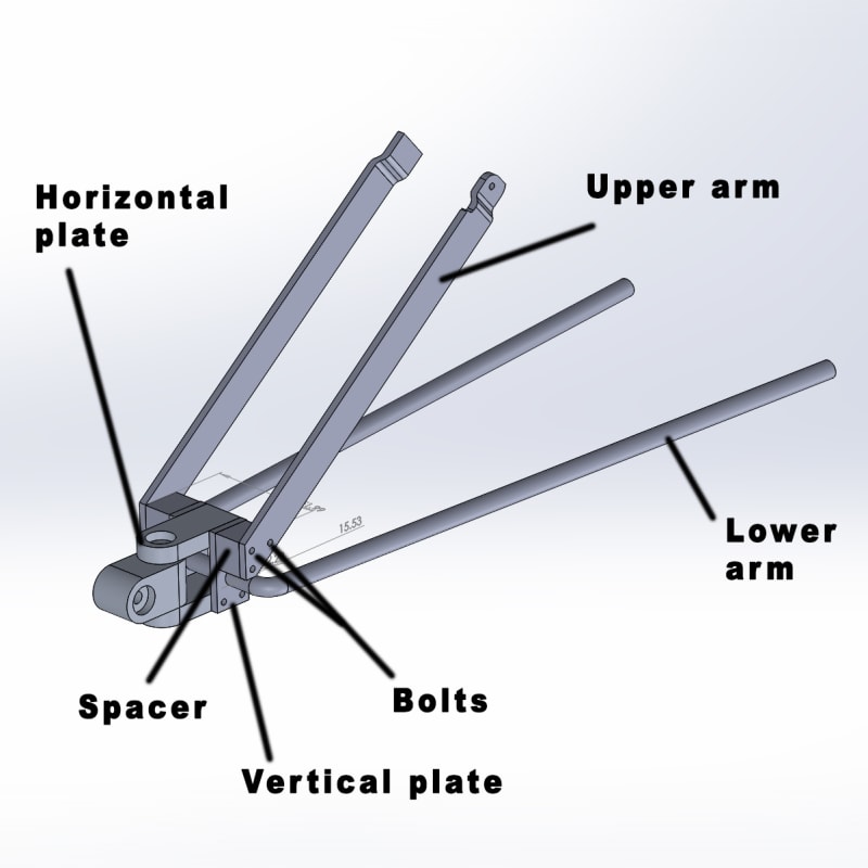
The problem: what is the maximum stress acting on each of the two bolts, as labelled in the diagram? (A third, lower, bolt connects the upper arm to the spacer, and the spacer to the vertical plate, below the two main bolts. It does not pass through the entire assembly as the other two bolts do, and it is repeated on the other side.)

I am designing a trailer hitch for a motorcycle. When analysing stress in the bolt, I am wondering how best to go about it. The bolt passes through the upper arm, the spacer, the vertical plate, and the horizontal plate, and then passes through the opposing vertical plate, spacer and upper arm, as illustrated in the above diagram. The load originates, for the purposes of this analysis, at the horizontal plate. The bolt is, therefore, enclosed within all of these respective components, which restrict its bending.
For the analysis, should the force be applied in the centre of the bolt (beam) representing the horizontal plate, and the remaining length, on either side, constrained? Or, should the spacers and vertical plates be neglected so that only the ends of the bolt where they attach to the upper arms be constrained?
I have been using FEA software that is new to me, and which I am yet to be confident in. It is giving me a wide range of values depending on how I constrain the bolt. The basic manual/traditional formula I used is
stress = (moment * radius of bolt) / I
My calculation was only in acceptable agreement with my FEA analyses when I constrained the entire bolt other than the length of its centre, where it mates with the horizontal plate and where the force was applied. When the model was constrained differently, such as only where the bolt mates with the upper arms, FEA predicted significantly less stress, which, to me, is counter-intuitive.
I really would be grateful for a little guidance on this, to restart my brain. Thanks.
The problem: what is the maximum stress acting on each of the two bolts, as labelled in the diagram? (A third, lower, bolt connects the upper arm to the spacer, and the spacer to the vertical plate, below the two main bolts. It does not pass through the entire assembly as the other two bolts do, and it is repeated on the other side.)

I am designing a trailer hitch for a motorcycle. When analysing stress in the bolt, I am wondering how best to go about it. The bolt passes through the upper arm, the spacer, the vertical plate, and the horizontal plate, and then passes through the opposing vertical plate, spacer and upper arm, as illustrated in the above diagram. The load originates, for the purposes of this analysis, at the horizontal plate. The bolt is, therefore, enclosed within all of these respective components, which restrict its bending.
For the analysis, should the force be applied in the centre of the bolt (beam) representing the horizontal plate, and the remaining length, on either side, constrained? Or, should the spacers and vertical plates be neglected so that only the ends of the bolt where they attach to the upper arms be constrained?
I have been using FEA software that is new to me, and which I am yet to be confident in. It is giving me a wide range of values depending on how I constrain the bolt. The basic manual/traditional formula I used is
stress = (moment * radius of bolt) / I
My calculation was only in acceptable agreement with my FEA analyses when I constrained the entire bolt other than the length of its centre, where it mates with the horizontal plate and where the force was applied. When the model was constrained differently, such as only where the bolt mates with the upper arms, FEA predicted significantly less stress, which, to me, is counter-intuitive.
I really would be grateful for a little guidance on this, to restart my brain. Thanks.


