Eng-Tips is the largest engineering community on the Internet

Intelligent Work Forums for Engineering Professionals

Virtual condition 1

Status
Not open for further replies.

3DDave

Aerospace
May 23, 2013
10,569
1
38
US
Suppose there is a basic brick shape - Datum feature A uses the largest face, datum feature B uses the next largest face, and datum feature C uses one of the smallest faces.

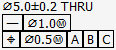
In the same face identified as datum feature A is a hole through the part of diameter E, positioned at MMB with [A|B|C] as the DRF with a tolerance of dia. X. Assume the basic dimension to B is b1, and the basic dimension to C is c1.

Now the face opposite of C is identified as datum feature D and is toleranced with a profile tolerance to [A|B|C] with a zone width of Y. Assume the basic dimension from C to D is d1.

The desire is to make a bracket sharply bent of a rectangular piece that mates to datum feature A, will have one edge coincident to datum feature B plane, and hook around the end of the part to mate with datum feature D. A bolt will pass through both parts.

What is the virtual size of that hole in the [A|B|D] DRF?
 
Replies continue below

Recommended for you

pmarc,

I agree, there are plenty of portions of Y14.5 which are "unclear/inconsistent/illogical/conflicting". The equations in Y14.5.1 seem to hold up in this case though.
 
pylfrm - to specifically answer your question - the allowed straightness is smaller than the position tolerance so it cannot cause the virtual condition to be any smaller and would not be subtracted in that case.

All right. I guess we agree that the position tolerance establishes a cylindrical boundary of diameter 4.3 in that case.

Now consider a hole specified as follows:

⌀5.0±0.2 THRU
[box]⏤[/box][box]⌀1.0Ⓜ[/box]
[box]⌖[/box][box]⌀0.5Ⓜ[/box][box]A[/box][box]B[/box][box]C[/box]

This scheme violates the following requirement:

ASME Y14.5-2009 para. 5.4.1.2 said:
Where the straightness tolerance is used in conjunction with an orientation tolerance or position tolerance value, the specified straightness tolerance value shall not be greater than the specified orientation or position tolerance value.

Would you say the tolerances have undefined meanings because the requirement is violated? If not, what exactly would you say the tolerances mean?


pylfrm
 
pylfrm - that clearly violates the requirement so the result is undefined.

Also firefox really hates whatever formatting is used to create those in-line diagrams.
 
In pylfrm's last example, both geometric tolerances and virtual conditions are defined, because each requirement is meaningful when considered with the size limits only. When combined, the result in terms of what variations are allowed is also quite clear.
The only problem is that only half of the straightness tolerance is usable. This is why there is a requirement in the standard not to assign the tolerance values that way.
 
3DDave,

I don't think violation of the requirement causes any problem for interpretation of the tolerances. I've always assumed that the only purpose of the requirement is to prohibit specification of a redundant tolerance.


This was the formatting:
[ignore]
⌀5.0±0.2 THRU
[box]⏤[/box][box]⌀1.0Ⓜ[/box]
[box]⌖[/box][box]⌀0.5Ⓜ[/box][box]A[/box][box]B[/box][box]C[/box][/ignore]

And this is how it looks for me in Firefox:

firefox_jhnmhs.png


What is it doing on your end?


pylfrm
 
pylfrm said:
I've always assumed that the only purpose of the requirement is to prohibit specification of a redundant tolerance.

Quite accurate. To add to that, it should be stated in advance that this cannot be compared with the independency as an implied "infinite straightness tolerance", Because part of the independency being "redundant" not being allowed by the standard would logically mean that using independency in conjunction with a supplementary form tolerance is also not permitted. Independency only means perfect form at MMC is not required, so any means to prevent infinite form error do not "override" the circled "I" in any way.
 
pylfrm - that may be, but the "shall" is pretty clear in making the pairing undefined. Per the standard a user would be unable to tell which was the driving requirement - was a decimal place missed? Was a digit missed? No way to tell.

I just restarted Firefox and it feels much better now. I had gone to Chrome and the "straightness character was blank there as well, though marking it for "search with Google" showed it was straightness. Reloading the page a couple of times in Chrome finally fixed it. I wonder if the problem in both cases is that the browser was forced to search for the unicode characterset that matched that entry and both of them failed to do so. I expect the browser at your end had already encountered the in-line character because you were the one who posted it. Not so much always WYSIWYG as sometimes WYSIWTF.

This is what I was seeing:
for_pylfrm_gxbe4j.png
 
Yeah - I guess that would be the interpretation if the standard did not deal with that exact case for form tolerances when applied against a form tolerance exemption and did not deal with that exact case for location and orientation.

Someone is up early.
 
ASME Y14.5-2009 para. 5.4.1.2 said:
Where the straightness tolerance is used in conjunction with an orientation tolerance or position tolerance value, the specified straightness tolerance value shall not be greater than the specified orientation or position tolerance value.

I am assuming that according to this statement one would have to say that the following specification for a hole:

⌀5±0.2 THRU
[box]-[/box][box]⌀1[/box]
[box]⌖[/box][box]⌀0.5[/box][box]A[/box][box]B[/box][box]C[/box]

is a clear violation of the standard, correct?
 
3DDave said:
Per the standard a user would be unable to tell which was the driving requirement

The feature would have to conform to both requirements. Obviously, it is not allowed to accept a feature based on conforming to a requirement with the more loose tolerance when it doesn't conform to the more strict requirement. Interpretation is not the issue. The issue is a geometric tolerance specification which is partially redundant, which is something that the standard sees as a bad practice and tries to prevent.
 
"Shall" means only one thing in this context. If the requirement is violated the drawing is non-conforming, which means it is not interpretable per the standard. Obviously.
 
pmarc,

From what I can tell, pylfrm's specification would violate the 2018 standard but yours would not. This is because pylfrm's spec has tolerances at MMC and yours are RFS. Y14.5-2018 states that the straightness tolerance does not affect the boundary for tolerances at MMC or LMC, but does affect the boundary for tolerances RFS. The reasoning is that "because the straightness applied to a feature of size controls the derived median line, and position controls the axis of the unrelated AME, the form and position tolerances accumulate".

I believe this would mean that having the straightness tolerance value larger than the position tolerance value would be allowable, if the tolerances are RFS. I'm not saying that I agree with the logic of this at all, but this is what I think the interpretation per Y14.5-2018 would be.

Evan Janeshewski

Axymetrix Quality Engineering Inc.
 
Evan,

I was actually asking whether my specification would violate 2009 standard. I know it doesn't violate 2018 and I don't think it should be prohibited in 2009. But apparently it is if we read the quoted statement from para. 5.4.1.2 literally, without a dose of scepticism.

This is all just to show that the rules in the standard cannot be blindly trusted and that in the process of making these rules it might have happened that not everything was envisioned and carefully thought out.
 
pmarc,
The specification you showed does violate the 2009 standard, from the reasons already mentioned for the MMC option.

The straightness tolerance creates an inner boundary (1.3.2) for the straightness of the hole of dia. 4.8-1=3.8.

The position tolerance creates an inner boundary for the position of the hole of dia. 4.8-0.5=4.3.

It is true that the two boundaries are different requirements as one controls the axis and the other the DML, and one is oriented and located to the DRF while the other is not. Nevertheless, the two boundaries can not coexist without the straightness tolerance being partially redundant as there will be no hole that can fully utilize the entire straightness tolerance without violating the position requirement.

In fact, the only difference in that sense between the MMC case and the RFS case is more tolerance for the feature in the intermediate UAME sizes of the feature, for each tolerance with modified material condition.
 
My analysis above is not true because there can be a hole as bent as the full straightness tolerance allows and with the UAME axis perfectly located and oriented to the DRF.

Therefore I agree and also don't think it should have been prohibited in 2009.
At least we know that some of the mistakes that are made a corrected in subsequent revisions.
 
pmarc,

You're right, the spec with RFS would violate the 2009 (and 1994) standard.

Here's another way to look at the issue. Let's say that we change the tolerances on feature D in Fig. 4-16 to apply the "zero position tolerance at MMC" approach:

Dia. 7 +/- 0.1
POS|dia 0.4(M)|A|B(M)|C(M)|

gets changed to

Dia. 7 +0.5 -0.1
POS|dia 0(M)|A|B(M)|C(M)|

Now, by Y14.5's rule, we are not allowed to specify a straightness tolerance at MMC at all.

I was wondering why they would define things this way. Is it because if the straightness tolerance was additive to the boundary, then this would allow more location error? The gage can't discern between form error and location error.

Evan Janeshewski

Axymetrix Quality Engineering Inc.
 
It is because the position VC protects an unviolated boundary of 7.5, ideally for a good functional reason. A DML straightness specified with any tolerance value would imply that this boundary can be violated, because of the rule #1 override.
Practically, if it was not forbidden, the straightness tolerance would be unusable.
 
Burunduk said:
At least we know that some of the mistakes that are made a corrected in subsequent revisions.

On the same token... Not sure if you have access to the draft of new Y14.5.1 that was released for a public review some time ago, but in that document the committee added two new methods for evaluation of the actual local size (in addition to the swept-spheres method):
1) based on opposing points (two-point method);
2) based on circular elements.

If you were to make a best guess, why did they decide to do that?


Evan said:
I was wondering why they would define things this way. Is it because if the straightness tolerance was additive to the boundary, then this would allow more location error?

I wouldn't see anything strange in disallowing application of additional DML straightness tolerance at MMC in conjuction with |POS|dia 0(M)|A|B(M)|C(M)| if the surface interpretation was the only possible interpretation for straightness and position tolerances at MMC. But since another interpretation, resolved geometry, is allowed per the 2009 standard as well, I guess this is what creates the dilemma.
 
pmarc said:
If you were to make a best guess, why did they decide to do that?

I have no access to the document but it was mentioned in one of the threads here.
Regarding the two-point method, it makes sense because this is what defines size in Y14.5 (ALS), and this is how most of the industry works, so it's about time ALS was fully defined. If I'm not mistaken the definition of what the cross-sections need to be taken normal to is still not very clear, but some sort of spine/curve is mentioned. If it's something different from how simple measurement devices work, it is useless.
 
Burunduk said:
Regarding the two-point method, it makes sense because this is what defines size in Y14.5 (ALS), and this is how most of the industry works, so it's about time ALS was fully defined.

That's one of the reasons but the more generic answer is that they wanted to provide means to deal with the cases where the default swept-spheres method for evaluation of size limits simply didn't work.
 
Status
Not open for further replies.
Back
Top