Tek-Tips is the largest IT community on the Internet today!
Members share and learn making Tek-Tips Forums the best source of peer-reviewed technical information on the Internet!
-
Congratulations TugboatEng on being selected by the Eng-Tips community for having the most helpful posts in the forums last week. Way to Go!
Wide flange with stiffener plates against Torsion? 8
- Thread starter planc
- Start date

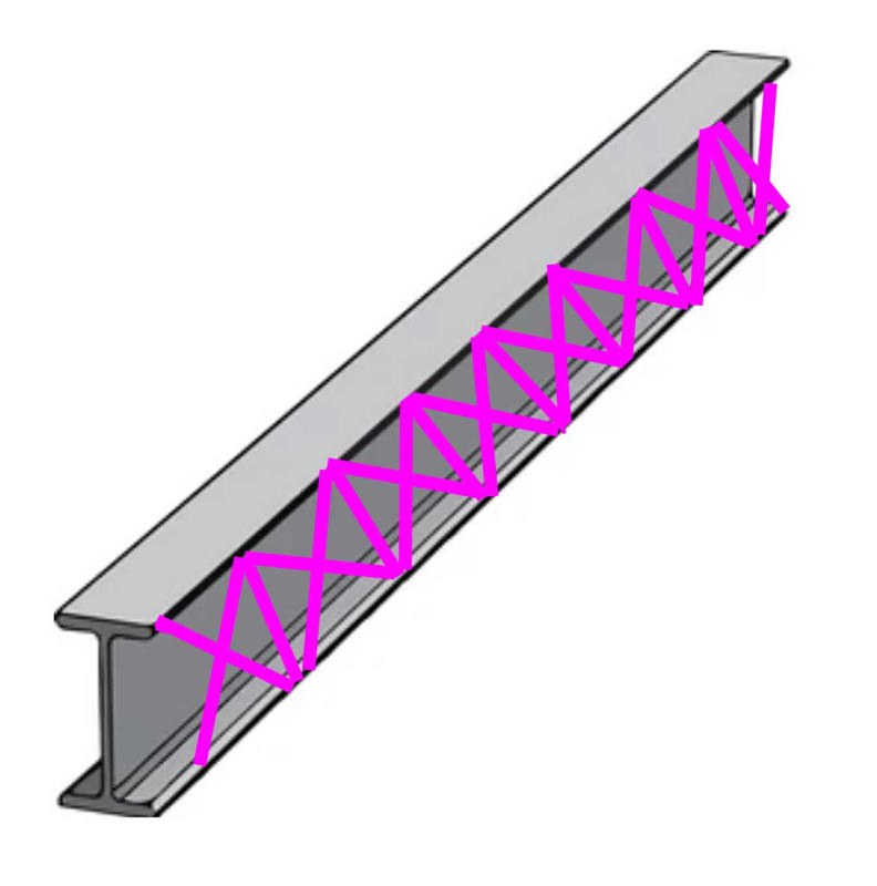
![[smile]](/data/assets/smilies/smile.gif "[smile] [smile]") But yes: stiffeners are pretty much useless for restraining torsion. The only reason I got into it is because I had a beam subjected to 100-200 ft-kips of torsion. (Special order wide flanges.) And I was wondering about the weld of the various stiffeners to the beam. (I.e. what force they would have to resist because of the torsion.) Turns out my worries were not justified....because the stiffeners didn't do anything as far as torsion goes. (Not without ridiculous spacing.)
But yes: stiffeners are pretty much useless for restraining torsion. The only reason I got into it is because I had a beam subjected to 100-200 ft-kips of torsion. (Special order wide flanges.) And I was wondering about the weld of the various stiffeners to the beam. (I.e. what force they would have to resist because of the torsion.) Turns out my worries were not justified....because the stiffeners didn't do anything as far as torsion goes. (Not without ridiculous spacing.)Similar threads
- Locked
- Question
- Locked
- Question