Continue to Site

Eng-Tips is the largest engineering community on the Internet

Intelligent Work Forums for Engineering Professionals

  • Congratulations KootK on being selected by the Eng-Tips community for having the most helpful posts in the forums last week. Way to Go!

Wide flange with stiffener plates against Torsion? 8

Status
Not open for further replies.

planc

Structural
Mar 3, 2022
64
Ibeam_with_plates_uvcggu.jpg


can putting such stiffener plates inside the web and flange (illustrated above) produce restrain against torsion? What is the formula for the spacing of the plates?
 
Replies continue below

Recommended for you

Planc said:
LIke what for example? The ends of the parapet will be connected to steel extended from column.

I mean having the parapet span across between those posts, as opposed to cantilevering up off the beam.
 
planc said:
So given the w8x21 is very small, and has poor torsion, how do you strengthen its torsion if not for plates or trusses. You are saying the plates are only viable solution?
1) I certainly feel that continuous plate reinforcement is the most viable option on the table.

2) If you scan this thread carefully, you'll see that I've suggested a number of options besides plating and trussing. Presently, I can think of no other options.
 
@planc:

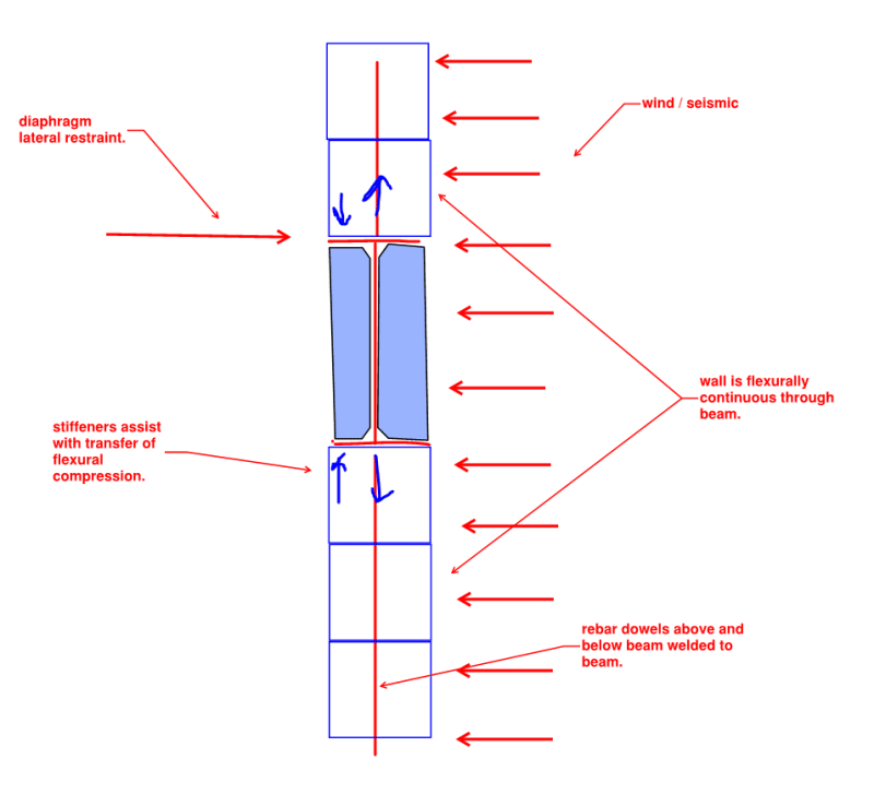
Now that we fully understand your situation, I think that the solution is quite simple. Per the sketch below, you can make the wall flexurally continuous across the beam such that the beam has no meaningful torsional requirement (granted the rebar welds are atrocious). With this solution, the stiffeners would indeed perform a useful function. This may well have been what your local engineer meant in the first place when they told you that there wasn't really a torsion issue to be concerned about.

This is precisely what is insidious about non-structural engineers asking structural engineering questions here. You've had group of highly skilled, highly paid professionals generously donating their time trying to help you out. Meanwhile, there was never really a problem to begin with. You simply do not possess the technical prowess required to recognize that. And thus we've wasted our time and energy on this non-issue when it could have been spent on more fruitful endeavors. In this sense, you've stolen from us by misusing this forum.

I've no doubt that you will fail to grasp the meaning of my sketch below. Don't waste your time asking me to explain it further. I've done more bear feeding than I'm comfortable with already.

c01_nzicae.png
 
KootK - rough day at the office?

You should stick around at least long enough for stripez/pixy/planc to tell you there's no diaphragm connection so you're wrong and you need to come up with another fix for his building...right now! Oh, and stick around a little longer and you can be the next one blamed for derailing his project for an entire year. Oh, and also accused of somehow being aligned with the Russians in the war against Ukraine. Not sure how I forgot that one!
 
phanENG said:
KootK - rough day at the office?

Rough day/week here. This may predate the rise of phamENG but, a few years back, I got bear baited into a 200+ post thread where I basically got tricked into designing a mid-rise concrete building in the Philippines for a contractor with a pathological distrust for his local engineering community. Shame on me of course. I suspect that that planc is still that guy and that this is actually still that building. As you can tell, I'm still harboring some ill will over that previous incident.
 
KootK said:
I suspect that that planc is still that guy and that this is actually still that building.

Sounds about right.
 
Kootk
Now that we fully understand your situation, I think that the solution is quite simple. Per the sketch below, you can make the wall flexurally continuous across the beam such that the beam has no meaningful torsional requirement (granted the rebar welds are atrocious). With this solution, the stiffeners would indeed perform a useful function. This may well have been what your local engineer meant in the first place when they told you that there wasn't really a torsion issue to be concerned about.


oKzW59.jpg


As shown in the above roof plan. The roof is thin metal sheet and has no diaphgram or brace to the left and right side 5.5 m span Ibeam (upper left which is the concerned now) that will support the 39" parapet. The small horizontal elements at middle are only sagrods that connects between purlins. And there was an thin aluminum gutter on the side of the Ibeam which can't restrain the ibeam. The rafters are connected from center ridge to the columns only. BAretired taught me the importance of distributing the rafters to the Ibeam to restrain it from torsion. But the advice was given after the structure already built.

So it is due to this lack of diaphgram or brace whatsover that needs torsional reinforcement so the ibeam can independent resist itself without brace/diaphgram restrain. And it needs to be done now before tenants would occupy it for the next 10 years.

That's not all. Almost all our welders are very poor people who don't have money even for 3 days without work. So I can't let them touch the inside of the flange lest they turn it into molten iron and weaken it. So I can only use support on the outside flanges. Plates covering the sides would have been the best solution but the only company selling the plate was not willing to cut it. So maybe best option would be to put thick plain bars or angle bars closedly spaced just on the flanges outer sides (like outside plates supposed to cover them).

I'm really sorry for bothering you guys, like Kootk, PhamEng and the regular folks, but in a country where structural engineers have for all intent and purposes no liabilities beyond 15 years except for gravity initiated falls only the first 15 years (like the slabs just falling to ground within 15 years). And no liabilities at all if seismic force hit us for any time. They would blame everything to the earthquakes if something fails. After 15 years. They are forever liability free for any building design shortcomings or damage. In the US, how many years are you guys liable?

Whatever, after this. I'd no longer bother you and give spaces to the new engineers being graduated now will help rebuild a nation (in ruins now). I will also share in our structural yearly magazine all the things I learn like not injecting liquid epoxy to large voids as the concrete can just collapse section in the void can collapse with only rebars holding them (thanks to Hokie elaborate explainations). Something most of our local engineering community can never understand. So by that fact alone you can save the future of our over 1000 50 storey buildings and even mid rise. Many predicted half will fail when the big one (seismic) came.

I don't mind any hostilities because in the world of science, only the truth, data, concrete (pun unintended) facts matter. All else are emotions that are not part of science. And I'm a scientist. Thank you all so much. I'd repay it one day.
 
Kootk,

@OP: I feel that the trussing idea needs to be abandoned given the size of your beam. It's just not viable for something as small as a W8x21. I was imagining something much larger when I proposed my trussing scheme.

This thread is entirely relevant because the wall below the I-beam and the I-beam bottom is not aligned!

This is because the columns were not aligned during construction. When the Ibeam was put 5 years ago. It was made straight like the green (where the blue now is the wall). The mid part where the center column is farther by 2.5" is where there is greater distance between the bottom wall and the I-beam.

a6DZwO.jpg


Here is the actual eccentricity. The green line where the I-beam flange appears. Notice the block at the open portion where it is only half the flange width (but all the wall rebars were welded to the flange center):

fij5a2.jpg


Or in terms of your illustration. Here is how it actually looks like with the proposed plate on the left or right side (again the mason just bent the rebars near the top of the wall to match the center of the flange):

PgHw4A.png


I will wait to get at least a 1/4" whole plate (or pieces welded together) to cover up all the sides to strengthen the shear as well as weak axis strength before putting any 39" high parapet, or abandon the parapet altogether. But I need to know one thing now. Why does the trussing idea needs to be abandoned for something as small as the w8x21? Why not viable?? Is it because the truss sections need to be so big as to be close to the whole plate? This is the last question, I need to know your valuable answer to either put a whole plate or abandon the parapet. Thanks Kootk!


Status
Not open for further replies.

Part and Inventory Search

Sponsor