Eng-Tips is the largest engineering community on the Internet

Intelligent Work Forums for Engineering Professionals

Will straightness affect the circularity and cylindricity? 2

Status
Not open for further replies.

SeasonLee

Mechanical
Sep 15, 2008
909
0
0
TW
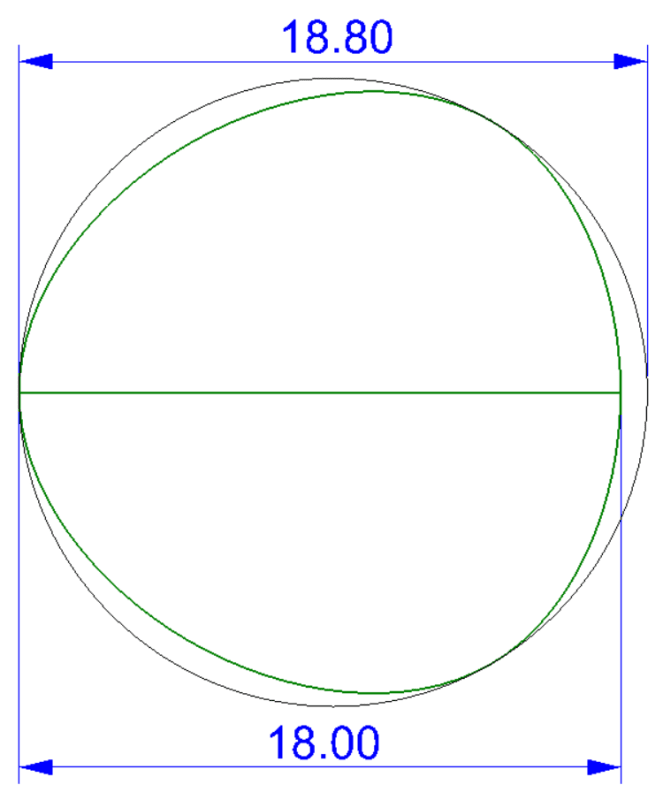
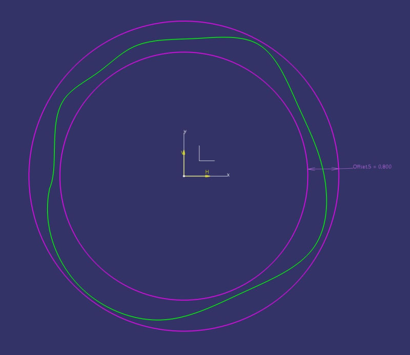
The figure below is a straightness callout on a shaft with a MMC modifier, but here I'm not talking about straightness, but circularity and cylindricity.

2023-11-08_jn3uzd.jpg


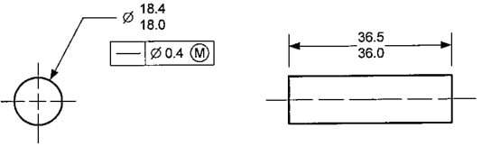
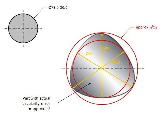
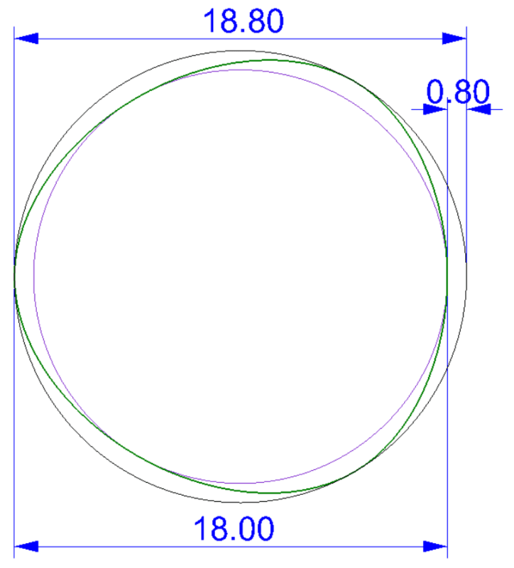
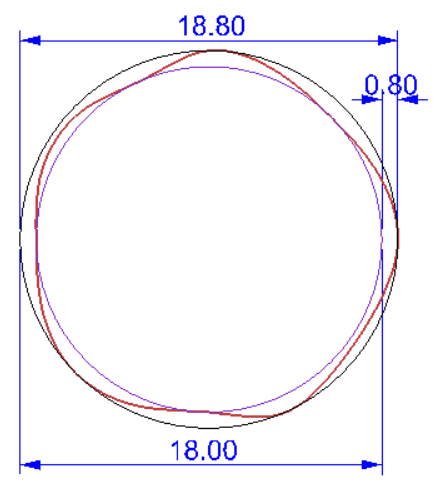
May I ask What are the maximum errors of circularity and cylindricity respectively.
Thanks for your help in advance

Season
 
Replies continue below

Recommended for you

Season,

Copy paste from 2018:
As each actual local size departs from MMC, an increase in the local diameter of the tolerance zone is allowed that is equal to the amount of this departure. Each circular element of the surface (i.e., actual local size) shall be within the specified limits of size.
This is circularity. Still 0.4 because the MMC bonus applies to the axis.

However in my understanding the cylindricity will be 0.8 because as the local size departs to LMC the axis tol zone will be 0.4 larger thus allowing more banana/barrel/wobble error while still maintaining 0.4 circularity but less in local size. And it's contained by the virtual condition boundary of D18.8.
 
SeasonLee,

Your question about the circularity and cylindricity error boils down to the questions of what size control means the absence of Rule #1, and what actual local size really is. These questions have been debated endlessly for many years in the standards committees and on this forum, and still have not been satisfactorily resolved. The figures in Y14.5 for size and straightness still only show side views, and do not show what happens within the cross section.

I would say that removing the Rule #1 boundary (or opening it up by a finite amount as in your example) affects the indirect control of all of the applicable form characteristics. So the circularity and cylindricity (and line element straightness) would be controlled within 0.8. There is strong evidence in the text of Y14.5-2018 to support this assertion.

Others would say that the form characteristics along the length of the feature (straightness) would be affected, but form characteristics within the cross section (circularity, cylindricity) would still be controlled within 0.4. There is also evidence in the text of Y14.5-2018 to support this assertion, but I would say that it is not convincing.

So unfortunately, the answer is going to be "it depends who you ask".

Evan Janeshewski

Axymetrix Quality Engineering Inc.
 
greenimi,

Or (your favorite subject) if this question comes up for the certification exam, what is the "correct" answer?

Ha! Certification is for parroting the wording from the standard, not speculating on equivalences. Isn't a passing grade 80%? Take a pass or just guess. It won't make a difference if the parroting goes well.

SeasonLee,

a picture is worth 1000 words.
 
Evan said:
The figures in Y14.5 for size and straightness still only show side views, and do not show what happens within the cross section.

Although I got all the answers I wanted, I still don't understand why the straightness error on the axis will affect the form (circularity, cylindricity). I'm really looking forward to someone being willing to provide a sketch on this “cross section” to interpret how it works.

3Ddave

Is this what you said “a picture is worth 1000 words”.

Thanks again

Season
 
Season,
Draw something like this in CAD with dimension X being 18, and a circumscribed circle 18.8 (because the VC boundary for straightness limits the form along the shaft and at every cross section without rule #1 intact). Then you figure out what the possible circularity error is.
 
SeasonLee,

Here is another example of what can happen within the cross section. The Straightness tolerance cancels the Rule #1 boundary (18.4) and imposes a larger boundary instead (18.8).

The actual local size can still be as small as 18.0, so the feature can be lobed more than it could with the Rule #1 boundary. The circularity value in this case is 0.8.

LobedSize_pwzorh.png


Evan Janeshewski

Axymetrix Quality Engineering Inc.
 
Evan (axym),

axym said:
Here is another example of what can happen within the cross section. The Straightness tolerance cancels the Rule #1 boundary (18.4) and imposes a larger boundary instead (18.8).

The actual local size can still be as small as 18.0, so the feature can be lobed more than it could with the Rule #1 boundary. The circularity value in this case is 0.8.

How do you know that the circularity value in this case is 0.8?
Asking to clarify my own doubts.

I attached two threads:

Per this discussion, seems a little off your calculation.....

independency_circularity_2_1_kwptvn.jpg


CREDIT to PMARC
has been discussed here:
 
greenimi,

I know that the circularity value in this case is 0.8 because I drew the feature that way ;^). Here is another figure showing the two concentric circles for an actual circularity zone:

LobedCircularity_tqwy7l.png


This analysis contains the assumption that an actual local size is a 2-point diameter. What specifically did you think was off in the calculation? I haven't had time to read through the thread you referenced.

Evan Janeshewski

Axymetrix Quality Engineering Inc.
 
I think greemini's last figure taken from the referenced thread is misleading in a way that when talking about circularity, the true profile of the part's cross section is a circle. The actual profile could be something that LOOKS LIKE a lobed part, and not one that's DESIGNED TO BE a lobe. Like that filleted tri-lobe. Or the Reuleaux triangle that's also mentioned in that thread.
These are not circular parts thus calling out circularity, or even PROVING circularity is VERY MISLEADING. They are wrong examples of explanation.
 
Wushee,

Interesting comment, I didn't think of the rounded triangle shape as being intentional but I suppose it could be. There are definitely situations when the shape was supposed to be round but was accidentally produced with the tri-lobe shape.

The figure doesn't have to be a 3-lobed shape - it's just the easiest shape to draw ;^). The cross section needs to be lobed to a certain extent, in order to show the maximum circularity error. There need to be high points, with a corresponding low point on the opposite side. But the shap doesn't have to be a Reuleaux triangle. Here's a more randomly lobed shape that shows the same effect:

LobedCircularity2_ftof2x.png


Evan Janeshewski

Axymetrix Quality Engineering Inc.
 
Evan, my problem is that many textbook examples show an extremely lobed polygon (likely purposefully, but it's confusing), others copied it therefore people on the forums got into arguments and started drawing more extreme examples based on the 3 lobed polygon and they've arrived at the Reuleaux triangle and co.

For explanatory purposes, showing low-high opposing points is good, but one must not forget that in the real world, most circular parts would look something like this instead:
circ_sk1mfm.jpg
 
Evan and all,

Here is my understanding about circularity maximum error question asked by the OP
If DMLS at MMC is added then the circularity is released from the rule#1 and then could be vary to an amount around 15% to 30% of the feature nominal size value.
If all local 2 points size equal to Ø18 (for example) then this shaft has a circularity of 18+2.7 (15%) =20.7 or (after other authors 30% 18+5.4(30%) = 23.4)
So, if the OP’s original picture shaft has its nominal size of 18 produced perfectly straight tri-lobe can create a cylindrical outer boundary of 20.7 (with 15% calculation) or a cylindrical outer boundary of 23.4 (with 30% calculation)

So, again my understanding, is that the DMLS at MMC should be able to release all form errors (circularity included) from rule#1 (not just straightness, since rule#1 is nullified)

If I am wrong I will stand correctly! Please advise


Status
Not open for further replies.
Back
Top