Continue to Site

Eng-Tips is the largest engineering community on the Internet

Intelligent Work Forums for Engineering Professionals

  • Congratulations SDETERS on being selected by the Eng-Tips community for having the most helpful posts in the forums last week. Way to Go!

Wind Loads on Conveyor Covers

Status
Not open for further replies.

bootlegend

Structural
Mar 1, 2005
289
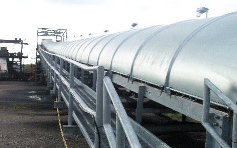
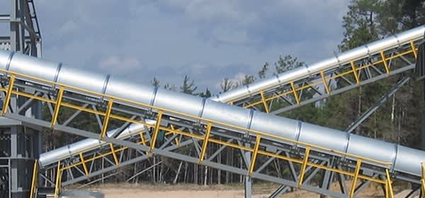
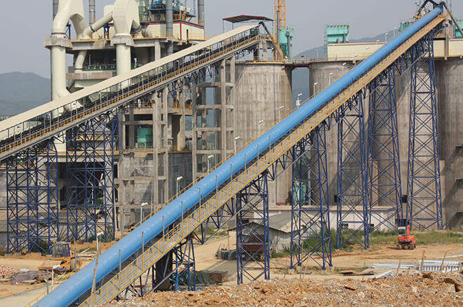
I'm looking for some opinions and approaches for methods of calculating wind loads on conveyor trusses and more specifically the arched belt "covers" that are sometimes attached to the truss. See the pictures for what I'm talking about.

Currently we are using ASCE 7-10 Figure 27.4-3 for arched roofs to calculate the external pressure coefficient. This chart is for enclosed and partially enclosed buildings and results in a substantial suction uplift on the hood. I'm questioning the applicability of this method and fishing for other approaches. The covers are open on the bottom and the spans are very short (maybe 6 feet max) compared to a building. It seems likely that the wind can pass through the truss meaning an open building pressure coefficient is more appropriate. I thought about approximating the arch as a pitched roof and using Figure 27.4-5 for pitched free roofs on open buildings. But noting the h/L ratio upper limit of 1.0 leads me to believe that these spans are just too short to develop much suction. My last rationalization is simply considering the entire truss and cover system as a whole and calling it a sign. I would not be calculating suction across the top of a sign so does it make sense to do so simply because the top is arched.

I appreciate any opinions.
conveyor-cover5_sb7yru.jpg

conveyorcovers_n9539b.jpg

Truoghed-Belt-Conveyor-Weather-Covers_vrgo9l.jpg
 
Replies continue below

Recommended for you

Wind can do some interesting things. Uplift is a meaningful possibility here, but the next questions would it even matter? Surely there is enough dead load present that uplift is a not a dominant factor even if it is present.
Meanwhile the lateral load across the conveyor and trusses is very much a dominant design load and will lead to moment and uplift on the supports upwind side of the conveyors. This wind effect is so dominant, most other effects are close to negligible.

(For what it is worth. I regularly calculate wind loads and design conveying gantries and supports. I've never bothered considering uplift (or downlit for that matter which can be just as likely depending on the shape. That said, just because I have experience with this type of structures doesn't make my right!)


bootlegend said:
But noting the h/L ratio upper limit of 1.0 leads me to believe that these spans are just too short to develop much suction. My last rationalization is simply considering the entire truss and cover system as a whole and calling it a sign. I would not be calculating suction across the top of a sign so does it make sense to do so simply because the top is arched.
I don't agree with that logic. A wing can be short and develop lift. If you get a fast moving flow of air on one side of a object than another then you can get a pressure differential, it keeps airplanes in the air! Nor do I agree with calling it a sign.

I'd call it what it is, it is a multimember frame with a curved top. I'd treat the conveyor the curved top as a single projected areas with a drag coefficient somewhere between 1.2 and 2.0. (I'd be confortable with 1.5). I'd treat the truss frame underneath member by member and calculate accordingly. I find dealing with wind loads on trussed frames an annoyance, I always like to sanity check my results by comparing it to the wind loads of fully enclosed structure of the same exterior dimension. 50-75% is what I've found as typical and reasonable. Though your experience may vary.
 
For the covers I'm looking at the uplift is larger than the dead load of the cover since they are made of 22 gauge steel. It has an effect on the foundation by adding another projected surface for wind load shear and reducing the gravity load resisting overturning.
human909 said:
I'd treat the conveyor the curved top as a single projected areas with a drag coefficient somewhere between 1.2 and 2.0. (I'd be confortable with 1.5).
human909 said:
comparing it to the wind loads of fully enclosed structure of the same exterior dimension. 50-75%
Thanks. I have tabulated wind loads separately for the truss (trussed tower), the walkway (open sign), the belt/idler profile projected area (open sign) at different heights and truss width/depths. Ideally I would like to add the cover as a separate option as well. I'll have to compare some actual numbers but I'm probably on the upper end of that range.
human909 said:
I find dealing with wind loads on trussed frames an annoyance
Agreed. Shielding,etc.


bootlegend said:
For the covers I'm looking at the uplift is larger than the dead load of the cover since they are made of 22 gauge steel. It has an effect on the foundation by adding another projected surface for wind load shear and reducing the gravity load resisting overturning.
So you are considering local forces. I'd absolutely consider the appropriate local wind uplift loads. I would have thought that the covers would be sufficiently well attached that uplift is irrelevant but if they aren't well attached I'd argue that could be an accident waiting to happen.

bootlegend said:
It has an effect on the foundation by adding another projected surface for wind load shear and reducing the gravity load resisting overturning.
True. But I'd expect it would be of the order of 1% or 2% if that.
 
Status
Not open for further replies.

Part and Inventory Search

Sponsor