Continue to Site

Eng-Tips is the largest engineering community on the Internet

Intelligent Work Forums for Engineering Professionals

  • Congratulations waross on being selected by the Eng-Tips community for having the most helpful posts in the forums last week. Way to Go!

Wood Roof - Thrust 9

Status
Not open for further replies.

Buleeek

Structural
Sep 5, 2017
98
Hi everyone,

I'm analyzing the TFEC Bulletin No. 2018-12 "Behavior of statically determinate and indeterminate rafters". If I use a collar tie (or strut) system (with no horizontal reaction at the bottom of the rafter)can I assume there will actually be NO horizontal force at the wall top plate? I know that collar ties should not be used to carry the thrust, but struts yes (located higher than top plate level in this case).

I am not sure what situation occurs in a real life. I can't assume that the rafter has no thrust at the bottom, since it is resting on the wall plate and is always notched/nailed/connected.

What do you usually do in such situation? That assumption determines a wall design and how much thrust it will carry.

Thanks,
 
Replies continue below

Recommended for you

Dik,

As requested. The collar ties 1s h/3 from ridge.

r_jtapw1.png
 
BA,

Very good picture with proper name for reference use.
 
Yup. There it is. Rafter tie tension went 70% higher and the moment in the rafter is now 12000 '# plus the deflections are vastly increased.

Nice Work. Thanks for that.

“What I told you was true ... from a certain point of view.” - Obi-Wan Kenobi, "Return of the Jedi"
 
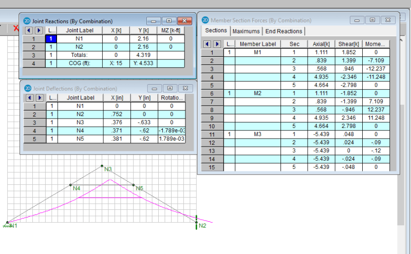
Those Risa results are very confusing. What is COG? Centre of gravity? I can understand the X value of 15, the c.o.g. of the structure no matter how it is defined. But I cannot understand the Y value which was 4.406 on the first run and 4.533 on the second run. I don't even know why the COG is important (unless I am not understanding what it means).

Why have the vertical reactions changed from 1.874k to 2.16k when the span hasn't changed? If the load is 0.1 k/ft, the total load is 3.0 kips, so the vertical reaction should be 1.5 k at N1 and N2 (formerly N3).

The maximum moment at the ridge is 3.0*30/8 = 11.25 'k. So the tension in the rafter tie should be 11.25/d = 5.439 k (Risa output). That would suggest that d = 2.068', so h = 3d = 6.205'.

Counting the grid-lines on the latest output, ridge point N3 appears to be 15' right and 9' above point N1. Coordinates are not shown on the sketch, so I may be misinterpreting something.

So, what gives? It is all very amoozin' and confoosin'.

BA
 
ax1e said:
Yup. There it is. Rafter tie tension went 70% higher and the moment in the rafter is now 12000 '# plus the deflections are vastly increased.

Actually, the tie force reversed from compression to tension.

BA
 
The reason is for the difference is largely due to different member properties assigned. The member stiffness of the latest model is twice of that for the first model, otherwise the deflection will slide out of page (too large), and the ridge become a curb on grade :) Same load though.

I just wat to demonstrate the effects of these two type of ties, sorry for the confusion.
 
Thanks I didn't notice the change in sign, but unless your axial load sign convention is backwards from mine Tension (+) compression (-), the first was tension and the second analysis shows compression. That said, I'm not seeing why it is in compression, especially if that is a roller on the right hand support. It seems like every member should be trying to keep that from rolling farther away and the moment from the vertical reactions should be trying to rip those rafters off the cross tie at connections N4 & 5

“What I told you was true ... from a certain point of view.” - Obi-Wan Kenobi, "Return of the Jedi"
 
Conventional coordinate system is use. +X is pointing right, +Y is up. Check member forces (M3, runs left to right), the second report shows the tie in tension, the first is in compression.
 
Thanks retired13... thought the tie might reverse forces... rigidity provided by diaphragm action of the gable end walls and the roof sheathing perhaps.


Dik
 
Dik,

Yes. I think so. Also the stiffness and location of of the tie play a significant role in minimizing the outward movement. In my model, I adjust the stiffness of the rafter, but did not bother to revise it for the tie. In reality, the tie will at least have the same stiffness of the rafter, so would be more rigid.
 
dik said:
Thanks retired13... thought the tie might reverse forces... rigidity provided by diaphragm action of the gable end walls and the roof sheathing perhaps.

The computer did not consider diaphragm action of walls or roof. It considered only the statically determinate structure depicted in the sketch by retired13. The tie force can be calculated easily by hand as M/d where M is the simple span moment WL/8 and d is the vertical distance from rafter tie to ridge. A computer is not needed. Same is true for the end reactions which are each equal to W/2.

From the RISA output, we can see that W = 4.32 kips, so the vertical reaction at N1 and N2 is 2.16 kips.

If L = 30', then M = 4.32*30/8 = 16.2k'
so d must be 16.2/5.439 = 2.98' (say 3')
Since d = h/3, h must be 8.94' (say 9')

If diaphragm action of roof and end walls had been considered, we don't know what the result might be. A stress reversal is certainly a possibility. But, as previously mentioned by others, diaphragm action is not something which engineers want to rely upon for reasons given by KootK in an earlier post.

BA
 
retired13 (Civil/Environmental)
10 Jun 20 22:08
Conventional coordinate system is use. +X is pointing right, +Y is up. Check member forces (M3, runs left to right), the second report shows the tie in tension, the first is in compression.

Sorry to be a pain, but do these not show the opposite to what you say,
First Analysis 9 Jun 20 21:40 M3 (+) 3.183K TENSION
Second Analysis 10 Jun 20 16:43 M3 (-) 5.139K COMPRESSION

Something is not right here? Maybe this is why I left structural for the petroleum industry!


“What I told you was true ... from a certain point of view.” - Obi-Wan Kenobi, "Return of the Jedi"
 
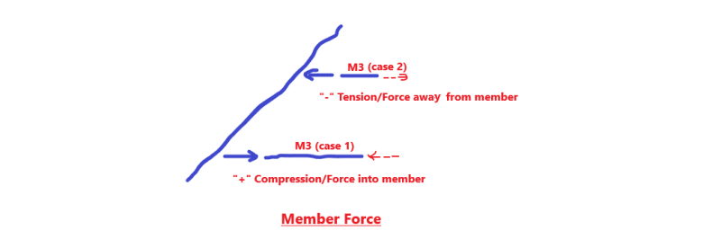
Don't confuse member forces with joint forces (note the report title "member section forces"). M3 is modelled from left to right, so "+" is compression into the member, and "-" means the force is against the direction of the x-axis, thus produce tension in the member. You are correct, if the report is for joint forces, which are reverse of the member forces.
 
I understand the joint forces, but I can't understand that sign convention for members. I was taught that member forces are always given in the local coordinate system with +=tension and -=compression. But that is a good thing in the sense that my "intuition" tells me that ME3 Case II simply has to be in tension, so I am more than happy to see at least that is verified.

Thanks very much. I'm returning to pipe stress (space frames) where member stresses are always +tension and -compression. (I hope)


“What I told you was true ... from a certain point of view.” - Obi-Wan Kenobi, "Return of the Jedi"
 
ax1e said:
I was taught that member forces are always given in the local coordinate system with +=tension and -=compression.

See sketch below for direction of reported member forces (----> + local x).

f_xyn7qb.png
 
Yes that is as I understand it, as those arrows represent forces APPLIED to a member. My problem is with the list of "axial forces" where their sign refers to a direction rather than as being a tension or compression force.

When I see a title that says member section forces, I don't think of forces being applied to the member. I think of internal forces. That's apparently where I am going wrong. I think of those axial forces as being a force equivalent to
F = axial_stress X cross-sectional_area, with +=ten & -=compr stresses and their equivalent forces in that member.

“What I told you was true ... from a certain point of view.” - Obi-Wan Kenobi, "Return of the Jedi"
 
Yes. I admit there is a confusion on RISA's reporting method. I remember STAAD reports member force at starting node of a member section and at its ending node, so tension, or compression is very clear. But RISA chose to report the force flow in the member section from the starting node only, so the confusion. However, back to late 90s, STAAD had its own mess on reporting +/- force flow in an inclined member, too.

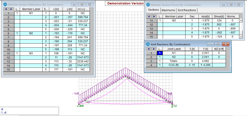
Anyway, I have made correction on model 1 as suggested by BA (release horizontal restraint). The result is shown below. Please note the sign change of force in/on M3. Again, sorry for stir up this confusion.

m_lsfm9n.png
 
Sign convention is just that: convention. It varies from program to program. Look at Staad if you want a real horror show. It covers all bases, but covers the most common bases poorly.

Image in 9 Jun 21:40 post: Both supports are fixed in position. These supports are stopping the spreading. Nodes N4 and N5 move closer under load so positive member axial force is compression.

Also note M3 sags so it appears that self-weight is applied. Remember that Retired13 said he changed the stiffness in the second analysis so the self-weight probably changed too. That's affecting the comparison a little. It would be better for this discussion of self-weight were removed.

 
Retired13, why is the total vertical load in your latest analysis (4.082k) less than in 10 Jun 16:43 analysis (4.319k)? Have you changed section properties again?

How much load is due to the 0.1k/ft we can see? Is it 3.0k based on the horizontal length, or 3.5k based on the inclined length?
 
steveh,

Good catch. Stiffer member was assigned to the second model to handle the huge deflections, that was explained in my response on10 Jun 20 18:35. This model was created in this morning with reduced stiffness in an effort to mimic the original model, but didn't get back to the original stiffness (4x12 vs 2x12). Yeah, seems I made a big mess here, but the concept is there.

I've not check into it yet, but I think RISA automatically assign/include member dead weight, if you select a member from their library. This time I selected wood material, the next time I shall try "general" type instead.

Thanks for the comment.
 
Status
Not open for further replies.

Part and Inventory Search

Sponsor