Continue to Site

Eng-Tips is the largest engineering community on the Internet

Intelligent Work Forums for Engineering Professionals

  • Congratulations waross on being selected by the Eng-Tips community for having the most helpful posts in the forums last week. Way to Go!

Wood Roof - Thrust 9

Status
Not open for further replies.

Buleeek

Structural
Sep 5, 2017
98
Hi everyone,

I'm analyzing the TFEC Bulletin No. 2018-12 "Behavior of statically determinate and indeterminate rafters". If I use a collar tie (or strut) system (with no horizontal reaction at the bottom of the rafter)can I assume there will actually be NO horizontal force at the wall top plate? I know that collar ties should not be used to carry the thrust, but struts yes (located higher than top plate level in this case).

I am not sure what situation occurs in a real life. I can't assume that the rafter has no thrust at the bottom, since it is resting on the wall plate and is always notched/nailed/connected.

What do you usually do in such situation? That assumption determines a wall design and how much thrust it will carry.

Thanks,
 
Replies continue below

Recommended for you

retired13
Those are roller supports (as per title) so no horizontal reactions. Horizontally restrained ends are on a different sheet.

“What I told you was true ... from a certain point of view.” - Obi-Wan Kenobi, "Return of the Jedi"
 
Sorry, I didn't notice that.
 
ax1e said:
But there seems to be a problem with balance of horizontal forces at B.
AB = 0
BCh = 870 compression * 12/12.65 = 875 left
BDh = 2727 tension to right
2727-875 = unbalance of 1902
What's going on with that?

Where did you come up with BCh = 870? It is incorrect.
The axial force in BC is variable because the applied load has a component parallel to BC.

Point C is a hinge, so the only thing holding it all together is the rafter tie with tension T.
WL/8 = Th where W = 2000#, L = 20' and h = 3.333-1.5 = 1.833'
From this, T is found to be 2727#.

Shear at C is zero, so point C feels a horizontal force of 2727# (compression) from BC and DC


BA
 
ax1e said:
I was looking for the tie force by sum horizontal forces at B
If BC is determined from sum vertical loads at C, gives BC axial load of 275/4*12.65 = 870 compression ????
Horizontal component is 870/12.65*12 = 825 ????
Then sum of horiz forces at B yields tie force of 825 tension ????
So you can't have the 2727 you get from sum of moments at C ????
The method is wrong and the results are wrong! See red question marks above.
You must have 2727 from sum of moments at C based on statics.

BA
 
Agreed. Summation of static forces in Fv and Fh must =0 everywhere.
Summation of moments at C method indicates that tie force must be 2727 tension.

However,

Summation of Fv at point C. Summing vertical forces at C must =0
(+) UP
The vertical point load from "beam BC" at point C is = -100 * (10-4.5)/2 = 275
Vertical component of BC at C = BC axial load /12.65 * 4
BC axial load /12.65 * 4 -275 = 0
BC axial load /12.65 * 4 = 275
BC axial load = 275 * 12.65 / 4
BC axial load = 870 (compression)

It follows that the Summation of Fh at B must also = 0
If tension in tie is 2727 (tension) a joint force to the right
The only other member with an axial load at joint B is BC with 870 compression (as per above)
That's 870/12.65 * 12 = 875 joint force to the left
[highlight #FCE94F]2727 - 825 = DOES NOT =0
Leaves an unbalanced horizontal of 1902 (to right)[/highlight]


“What I told you was true ... from a certain point of view.” - Obi-Wan Kenobi, "Return of the Jedi"
 
ax1e said:
The vertical point load from "beam BC" at point C is = -100 * (10-4.5)/2 = 275 (not true...it is zero)

Vertical component of BC at C = BC axial load /12.65 * 4
BC axial load /12.65 * 4 -275 = 0
BC axial load /12.65 * 4 = 275
BC axial load = 275 * 12.65 / 4
BC axial load = 870 (compression)
Your argument is based on a false premise, hence your statements are false and your conclusion is wrong.

Your starting point should be to calculate the force in the rafter tie using simple statics, namely T = M/h where M is the span moment, WL/8 and h is the vertical distance from BD to C.

I get the feeling I am beating a dead horse!


BA
 
Why is it not 275? I showed you how it was calculated based on the conversion of a uniform distributed load to equivalent joint loads.
If you don't like that method, then just assume that there are no uniform distributed loads on this structure at all and I hanged sand bags at each joint equal to
Sand bag at A 225
Sand bags at B 225 + 275 = 500 total
Sand bag at C 275

Now while we are at it, let's sum the vertical loads at joint B and see what the imbalance is there.
870 compression from CB - down = -870 / 12.65*4 = -275
-500 point load
AB axial load = 0
[highlight #FCE94F]Opps unbalance of -775[/highlight]

“What I told you was true ... from a certain point of view.” - Obi-Wan Kenobi, "Return of the Jedi"
 
Okay, let's go with the sandbag analogy...except that sandbag C should be 5.5(100) = 550#

So M = 500(4.5) + 550*20/4 = 5000'#
and M/h = 5000/(3.333-1.50) = 2727#

The result is the same.


BA
 
That sandbag weight was calculated from UDL of 100 * 1/2 * 4.5 + 100 * 1/2 * 5.5 = 225 + 275 = 500 [highlight #FCE94F]not 550[/highlight]

I agree that summation of moments at C results in tension of 2727
But I say that the summation of forces at each and every joint must be zero, or if not, the joint is moving.
Joint forces don't balance, so 2727 while correct is the correct force at the centerline of the tie member, it cannot be the correct force that the tie places on/at joint B.

“What I told you was true ... from a certain point of view.” - Obi-Wan Kenobi, "Return of the Jedi"
 
B to D is 11', so sandbag C should be 11*100/2 = 550#, not 500#.

I agree that the sum of H, V and M for every joint must be zero and I expect they are.

BA
 
B to D has no load. And D is on the other side of the centerline. The free body is only considering loads to the left of centerline and BD is cut directly below C.

B to C has a horizontal distance of 10-4.5 = 5.5
1/2 goes to B, 1/2 goes to C, 275 each one. 275 + 225 = 500 At least they are in Excel 2013

Exactly. They should all be zero, but [highlight #EF2929]the problem remains that the summations of Vs, Hs and Ms at joint B are NOT ZERO[/highlight].

“What I told you was true ... from a certain point of view.” - Obi-Wan Kenobi, "Return of the Jedi"
 
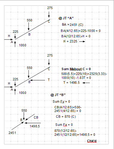
Here is my calculation assuming pin support. Let me know for mistakes. Thanks.

t_jr7sum.png
 
Sandbag A = 4.5*100/2 = 225
Sandbag B = 10*100/2 = 500
Sandbag C = 11*100/2 = 550 (275 to each side)

M = 500(4.5) + 550(20)/4 = 5000'#
When A and E are hinged (first diagram), H = 5000/3.3333= 1500 (not 2325) but this is not the case in this thread.

Second diagram, shows T (tension?) but arrow suggests compression. H value is not shown.
This is an indeterminate structure which depends on stiffness of members...can't be determined.

Third diagram - part of an indeterminate structure, so I cannot check it.

In our case, it is as I indicated in earlier posts. All joints satisfy the condition that Sum of H, V and M = 0.

M@B = 775*4.5 = 3487.5 (from forces at A)
M@B = 500*4.5*5.5/10 + 2727*1.5*1.8333/3.3333 = 3487.2 (Beam ABC moment)
M@B = 2727*1.8333 - (550/2)5.5 = 3487 (from forces at C)

BA
 
BA,

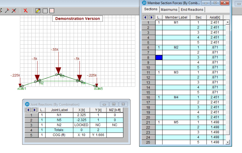
H is positive as the direction shown. Due to symmetry, the calculation was performed on half frame, assuming simple truss action. The results are verified use RISA.

RISA output
t1_auj0hh.png
 
retired13,

The structure you are showing above is pinned at each support. The top of a stud wall cannot resist a horizontal force of 2325#. I thought we had previously agreed that you should be using pin and roller. If you make one of your supports a horizontal roller, you will find the correct forces for the assumed geometry. I expect they will agree with my results.

The structure you are illustrating is indeterminate, which means you must assign stiffness to each member in order to find the correct solution. With pin/roller, the structure is determinate, so member stiffness does not come into play.

Just substitute a roller for one of the pins. Good luck!

BA
 
BA,

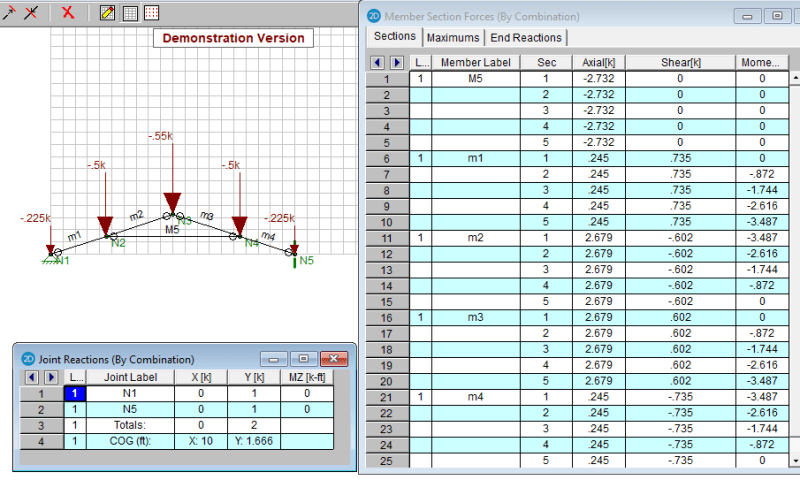
As mentioned, my last 2 analyses was performed on simple truss with axial force member only. Below is the model of your request, the rafters are single piece material with moment capacity, and one of the support is changed to roller.

t2_bkcpbk.png
 
retired13
17 Jun 20 00:04
That is correct, if the point load at B is 500, not the 550 you have shown, and there is a pinned support at A. Unfortunately, we were talking about a roller support at A. And, yes the arrow on the joint from BD's axial tension load should be reversed showing direction to the right. Unfortunately that change in direction unbalances the summation of
horizontal forces at B.
-870 /12.65 * 4 = -825
2451 /12.65 * 4 = +2325
1500 to right = +1500
[highlight #FCE94F]Sum Fh at B = +3000 that isn't 0
[/highlight]

BAretired
17 Jun 20 01:20
Sand bag at C is 275. We need only analyze 1/2 the structure, to the left of its centerline, therefore 275. The other half of the structure to the right of centerline takes the other 275, but we are not concerned about that half. There is no need to consider your additionall 275 load.

I am not sure why you have the 550(20)/4 in your line showing M = 500(4.5) + 550(20)/4 = 5000'#
The load is not 550 and the distance is not 20/4, so what is this?

Now, your lines,
M@B = 775*4.5 = 3487.5 (from forces at A)
M@B = 500*4.5*5.5/10 + 2727*1.5*1.8333/3.3333 = 3487.2 (Beam ABC moment)
M@B = 2727*1.8333 - (550/2)5.5 = 3487 (from forces at C)

The first line is OK, the internal moment at B is 3487.
But I don't understand what the second line is doing. Something about Pab/(L/2) and the tie force x h1 x h2 / h? Would you please explain what that is?
The third line appears to be balancing moments at C at the start, because 1.8333 * 2727 is the distance from C to tie and 2727 is the tie force, however you have written B). The distance from B to tie load is 0.
And finally the 550/2 (=275) point load placed 5.5 away from B could only be putting that load at C, indicating you are balancing B. So are you balancing moments at B or C? And I note that the net reaction at A of 775 up is not included at all, except in the first line.
I don't know why it takes 3 lines of different equations to balance moments at any point. One equation showing a sum of moments =0 will do. Then we can work on summing the Fv and Fh equations.

BAretired
17 Jun 20 04:20
" With pin/roller, the structure is determinate, so member stiffness does not come into play."
To ensure that the structure does not fall down, member stiffnesses of ABC and CDE must be relatively large. That's definitely in play.

Retired13
17 Jun 20 05:29

[highlight #FCE94F]Now we are getting somewhere. This is important.[/highlight]
M5 axial load is 2732. Good! Agrees closely with a sum moment at C solution.
M1 axial load is 245, not zero as a roller support might indicate in a determinate structure analysis, however the shear load in this member and moment at B must be doing the bulk of the work in resisting the 775 net load there at A without needing to generate a large axial load. Shear in M1 is 735, which is close enough for me to say that it is shear and bending moment are indeed resisting the net reaction load of 775. So not much axial force is needed to do so. So if we attempt to balance forces at B, we must not only consider axial loads, as in a truss. We must also consider the shear loads being dumped into that joint from members m1 and m2. [highlight #FCE94F]Shear loads dumping into joint C must also be considered when balancing Fh and Fv at joints of indeterminate structures we must consider Vh and Vv,[/highlight] not just the axial loads.

I have deleted the Dropbox file until such time that I can add shear loads into the joint balances.
Thank you both for the grey matter exercise. I am vary happy with the outcome. I'm good. Now I can analyze the indeterminate structure by assuming that any unbalanced axial forces must be resisted by adding the appropriate amount of shear into the respective members.


“What I told you was true ... from a certain point of view.” - Obi-Wan Kenobi, "Return of the Jedi"
 
ax1e said:
Sand bag at C is 275. We need only analyze 1/2 the structure, to the left of its centerline, therefore 275. The other half of the structure to the right of centerline takes the other 275, but we are not concerned about that half. There is no need to consider your additionall 275 load.

The sandbag at C must be 550. Half goes to each side. If the reactions at A, E are represented by a pin and a roller, you must consider both sides. Alternatively, you could consider a roller at A and E, but then you would need a horizontal support at C for stability.

ax1e said:
I am not sure why you have the 550(20)/4 in your line showing M = 500(4.5) + 550(20)/4 = 5000'#
The load is not 550 and the distance is not 20/4, so what is this?

It is the moment of the structure from A to E. If you consider a simple beam from A to E, M = Pb.a + Pc.L/4. This is the sandbag equivalent of WL/8 where W = 2000# and L = 20'.

ax1e said:
Now, your lines,
M@B = 775*4.5 = 3487.5 (from forces at A)
M@B = 500*4.5*5.5/10 + 2727*1.5*1.8333/3.3333 = 3487.2 (Beam ABC moment)
M@B = 2727*1.8333 - (550/2)5.5 = 3487 (from forces at C)

The first line is OK, the internal moment at B is 3487.
But I don't understand what the second line is doing. Something about Pab/(L/2) and the tie force x h1 x h2 / h? Would you please explain what that is?

Point B has two loads acting on it, namely Vb = 500# and Hb = 2727#
M@B = Vb.a.b/L + Hb.h1.h2/h
Its value agrees with two other ways of calculating M@B

ax1e said:
The third line appears to be balancing moments at C at the start, because 1.8333 * 2727 is the distance from C to tie and 2727 is the tie force, however you have written B). The distance from B to tie load is 0.
And finally the 550/2 (=275) point load placed 5.5 away from B could only be putting that load at C, indicating you are balancing B. So are you balancing moments at B or C? And I note that the net reaction at A of 775 up is not included at all, except in the first line.

There are two forces acting at C, Vc = 550/2 = 275# and Hc = 2727#.
The third line calculates their moment about point B.

ax1e said:
I don't know why it takes 3 lines of different equations to balance moments at any point. One equation showing a sum of moments =0 will do. Then we can work on summing the Fv and Fh equations.

It doesn't and ordinarily I wouldn't do it, but you persisted that things were not balancing, so I gave you the whole shmear.

Summing Fv and Fh is pretty straightforward, so I didn't include it.
For point B, Fv = 1000 @A - 225 @A - 500 @B - 550/2 @C = 0; Fh = 2727 @B - 2727 @C = 0


BA
 
ax1e said:
BAretired
17 Jun 20 04:20
" With pin/roller, the structure is determinate, so member stiffness does not come into play."
To ensure that the structure does not fall down, member stiffnesses of ABC and CDE must be relatively large. That's definitely in play.

Member strength is assumed to be adequate when designing a determinate structure. Member stiffness will affect deflections but will not affect forces and moments in the members.

When the structure becomes indeterminate, as it does when there are pins at A and E plus a tie (or strut) between B and D, member stiffness affects the magnitude of forces and moments.

BA
 
ax1e said:
Now we are getting somewhere. This is important.
M5 axial load is 2732. Good! Agrees closely with a sum moment at C solution.
M1 axial load is 245, not zero as a roller support might indicate in a determinate structure analysis, however the shear load in this member and moment at B must be doing the bulk of the work in resisting the 775 net load there at A without needing to generate a large axial load. Shear in M1 is 735, which is close enough for me to say that it is shear and bending moment are indeed resisting the net reaction load of 775. So not much axial force is needed to do so.
Slope = 4/12
theta = arctan(4/12) = 18.43[sup]o[/sup]
Va = 1000 - 225 = 775
M1[sub]axial[/sub] = 775sin(theta) = 245#; M1[sub]shear[/sub] = 775cos(theta) = 735#

ax1e said:
So if we attempt to balance forces at B, we must not only consider axial loads, as in a truss. We must also consider the shear loads being dumped into that joint from members m1 and m2. Shear loads dumping into joint C must also be considered when balancing Fh and Fv at joints of indeterminate structures we must consider Vh and Vv, not just the axial loads.

You don't need to consider axial and shear loads separately when you have the actual loads at your disposal as you do in the present case. The balance equation is easier than you think.

BA
 
Status
Not open for further replies.

Part and Inventory Search

Sponsor