Continue to Site

Eng-Tips is the largest engineering community on the Internet

Intelligent Work Forums for Engineering Professionals

  • Congratulations waross on being selected by the Eng-Tips community for having the most helpful posts in the forums last week. Way to Go!

BUCKLING FEA - The case of a 'pinned' base plate 4

Status
Not open for further replies.

human909

Structural
Mar 19, 2018
2,004
One thing that I've often been curious about is the buckling behaviour of a nominally pinned column under compression with a typical 'pinned' base plate.

Examples:
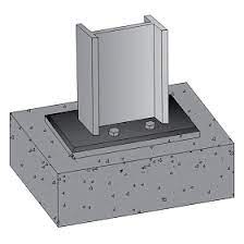
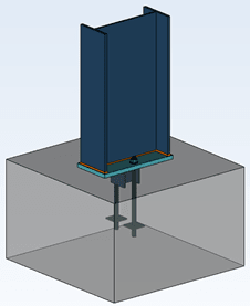
temp_lpzvch.jpg
temp2_zsevhq.png


For both of these I would consider these as 'pinned' connection and model them as such. Thus I'd would get zero moment transfer and effectively length of 1 if top of the column is braced but with no rotational restraint. As I understand it this is a pretty typical analysis approach under most codes and in most jurisdictions.

My question is:

Is this overly conservative? Would the compression and flat base plate not provide a degree of fixity and thus improve the critical buckling load? Here I define here a baseplate that is resting on a foundation but not restrained from uplift as a SEPPERABLE BASE PLATE.


It would surprise me if there isn't already plenty of literature on this matter. But I've never seen it. So I'd though I'd test it. And since I don't have a test laboratory at hand I figure I'd use FEA.

TEST APPROACH
-Non-linear plastic FEA analysis using NASTRAN
-Tri linear model of stress-strain curve used
-Iterative approach to converge on buckling solution (NASTRAN does have non-linear buckling analysis but not nonlinear PLASTIC buckling analysis)
-An additional lateral load of 1% of axial load was added to trigger the buckling. (This value is arbitrary but considered reasonable and conclusions not sensitive to this.)

TEST DETAILS
-Steel section: HEB160 S275 (EUROPEAN STEEL)
-Section length: 6600mm
-Minor axis translationally fixed, translationally fixed at the top, rotationally free.
-Base plate modelled in 3 ways; perfectly pinned; able separate but not slide AND; rigidly connected to foundation.
-Nominal mesh size - 50mm

CODE BUCKLING LIMIT:
Ncx = ~780kN (without any capacity reduction factor, both codes AS4100 and Eurocode within 2%)

FEA RESULTS
PINNED: Ncx = ~800kN
BASE PLATE (with sepparation): Ncx =~1150kN (equivalent le = 0.83)
BASE PLATE (RIGID): Ncx =~1150kN (equivalent le = 0.83)

As can be seen no discernible difference (<1% tolerance) between the rigidly connected base plate and a base plate with no uplift restraint.

CONCLUSION
In some/many circumstances it is not unreasonable to consider a typical column and base plate arrangement as 'fixed' for consideration of its buckling effective length. Without doing exhausting further testing I would suggest that this is reasonably representative for columns of 'intermediate slenderness' where inelastic buckling dominates.


ADDITIONAL TESTING
I was a little perturbed by the lack of discernible difference between a rigidly fixed base plate and one that is able to separate from its support. I hypothesised that this was due to inelastic buckling dominating before any appreciable rotation could occur at the base. This was tested by doubling the length of the HEB160 to 13200mm. To summarise this additional testing:
PINNED BASE = 275kN (Unreduced capacity in code 250kN)
BASE PLATE ON SURFACE = 460kN (equivalent le = 0.77)
FIXED BASE PLATE = 500kN (equivalent le = 0.74)

It was satisfying to see that for more slender columns the back calculated effective length approached the theoretical Euler elastic theoretical length. It was also satisfying to confirm that a fully fixed base base does exhibit better performance (as expected) compared to a separable base plate.


And here is a pretty FEA picture to keep everybody happy:
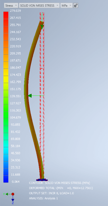
temp3_mzr32q.png
 
Replies continue below

Recommended for you

As well as a recurring curiosity part of the reason why I went to the trouble here was that this particular member in question was part of an OEM supplied pre fabricated structure. I found myself doing my due diligence on the supply and questioning the assumptions. Base on the OEM calculations the columns capacity are calculated using an effective length factor of k=0.7. Their engineers seem to be assuming fixed end at both ends in circumstances where I would normally not find it justifiable.

The results presented here seem to suggest their use of k=0.7 isn't beyond justification. IMO it is skirting the line of unconservatism, but not crossing it.

It isn't an assumption I'll likely make a habit of making.
 
There is an AISC document on base fixity, link can be found in this thread: Link

- Assuming your model is for a column on a foundation then one important aspect not accounted for in your model is the rotation of the foundation which will increase the overall base joint rotation.

 
AISC Specification Commentary also provides this guidance for G at foundations:
Screenshot_2022-10-31_095555_qzjpbz.png
 
how well does your FEM model the preload (between the column and the ground) ?
Does your FEM allow gapping ?

"Hoffen wir mal, dass alles gut geht !"
General Paulus, Nov 1942, outside Stalingrad after the launch of Operation Uranus.
 
human909 - nice work. I think it's important to keep the commentary that Celt83 posted in mind, though. Particularly this part:

AISC Spec that Celt83 Quoted said:
If the column end is rigidly attached to a properly designed footing

If I have a column that lands on an isolated, shallow footing that isn't designed to resist moment, the inherent rigidity between the "pinned" column base and the concrete is made less important by the rotation of the footing.

So if you've got this thing on a massive pad, a grade beam designed to/capable of resisting moment, or similar foundation that will be stiff with moment applied, this is an important consideration.
 
Isn't the British Standard to allow for 20% of the column stiffness at the base plate unless a more rigorous design methodology is used? So instead of pinned-pinned or pinned fixed you have pinned top with a spring at the bottom.

Again, the base plate and foundation needs to be properly designed for the developed moment.
 
If those bases didn't behave as fixed, you'd never be able to erect them. But if you want to account for them being fixed in the design, the whole system should be designed like it - anchors designed for the additional tension, footing designed for rotation, etc... doesn't strike me as worth the effort just to reduce the strong axis buckling length of a column.
 
Careful Canwest.. to a PEMB designer, those are fighting words!

(Assuming they've delegated the anchor and footing design back to the EOR)
 
A square ended column supported on a rigid surface has to axially shorten for rotation of the base to occur. This provides a rotational spring which helps constrain the buckling. If that rotational spring is much stiffer than the members flexural stiffness then the buckling load will be close to the fixed ended condition.
 
You need to place a lot of bolts a long distance away from the column neutral axis to develop the force couple (tension in bolts, compression in bolts and due to plate bearing) required to cause rotational fixity.

The figures you provide do not allow for great rotational restraint. The first setup (figure on the top left) has two bolts located close to the beam N.A. in both strong and weak axis directions. The second setup provides almost zero rotational restraint (bolt practically at N.A. in both directions), unless you somehow intend to count on the base plate adhesion to concrete or rebar.

It is not the column slenderness you should worry about. Rather, it is the local highly non-linear behavior of the joint (sliding and perpendicular contact between plate and concrete, bearing of bolts on plate, shear-tension-bending on bolts, rigidity of the beam-baseplate weld, plasticity etc.) which is of concern, and fancy FEA results will only give reasonable results if you also detail the joint to actually be able to generate a force couple and the accompanying stiffness against rotation.

If you want a moment joint, you'd at least need to consider:
a) self-weight and reinforcement of the footing, grade beam or slab (it needs to provide a monolithic anchor block which does not rotate with the column)
b) thickness of the base plate (thicker means more rigid, which provides more predictable stiffness)
c) spacing of bolts (they need to be far away from the beam N.A.)
d) amount of bolts
e) column-to-baseplate connection (a fillet weld is not always enough to prevent rotation; a triangular gusset plate or two on each edge may be required)
f) the direct bearing capacity of the beam flange and web against the base plate

In short, pinned connection is more conservative, less demanding to fabricate and certainly more applicable for the examples you provided.


Centondollar said:
You need to place a lot of bolts a long distance away from the column neutral axis to develop the force couple (tension in bolts, compression in bolts and due to plate bearing) required to cause rotational

The rotational fixity in this example is inherent in the geometry. Bolts are not required for rotational restraint to occur. It is akin to a brick wall on a concrete slab being considered fixed at the base.
 
Celt83 said:
There is an AISC document on base fixity, link can be found in this thread: Link

- Assuming your model is for a column on a foundation then one important aspect not accounted for in your model is the rotation of the foundation which will increase the overall base joint rotation.
Thanks for the document. And good point about the foundation. I have seen a PEMB end up with a rotated foundation due to inadequate restraint on the column.

rb1957 said:
how well does your FEM model the preload (between the column and the ground) ?
Does your FEM allow gapping ?
No preload was given. The FEM does allow gapping. The difference between allowing gapping and not can be seen in the last figures k=0.77 vs k=0.73.

phamENG said:
So if you've got this thing on a massive pad, a grade beam designed to/capable of resisting moment, or similar foundation that will be stiff with moment applied, this is an important consideration.
In the specific case being considered it is on a massive pad, the foundation is effectively rotationally restrained. That said, I have no intention of making a habit of relying this reduction in effective length. I am not happy that the OEM supplier have used this assumption and I have issued an RFI.

canwesteng said:
But if you want to account for them being fixed in the design, the whole system should be designed like it - anchors designed for the additional tension, footing designed for rotation, etc... doesn't strike me as worth the effort just to reduce the strong axis buckling length of a column.
That is the point the anchors DON'T need to be designed for rotation if you are just after a reduction in the effective length under axial compression.

centondollar said:
You need to place a lot of bolts a long distance away from the column neutral axis to develop the force couple (tension in bolts, compression in bolts and due to plate bearing) required to cause rotational fixity.
Normally that is what is taught. But this (and other analysis) shows that that is not accurate. You can achieve sufficient rigidity under axial compression in the end plate to foundation interface without ANY bolts restraining rotation.

centondollar said:
If you want a moment joint, you'd at least need to consider:
You have missed the point. I don't want a moment joint and at no stage did I set out to analyse a joint that could adequately transfer moment. What I did set out to examine was if the joint was sufficiently rigid to been considered as 'rigid' for purposes of calculating effective length under axial compression.

I've designed base plate moment connections in my time. And yes, big plates, big welds, big bolts and lots of them.
 
Human said:
FEA RESULTS
PINNED: Ncx = ~800kN
BASE PLATE (with sepparation): Ncx =~1150kN (equivalent le = 0.83)
BASE PLATE (RIGID): Ncx =~1150kN (equivalent le = 0.83)

The theoretical effective length for a true fixed base condition is 0.7. Why do you think the software is giving 0.83?
 
Tomfh said:
The theoretical effective length for a true fixed base condition is 0.7. Why do you think the software is giving 0.83?
Good question Tomfh.

The theoretical effective length for a true fixed base condition under ELASTIC buckling is 0.7. However here we have inelastic buckling occurring. As soon as we get into inelastic buckling we have lots of additional complications like what stress-strain plot to choose etc...

The software is giving a critical buckling load and I'm back calculating the equivalent effective length using the Euler elastic buckling formula and the calculated critical buckling factor for a true pinned connection. If I back calculated it using the slenderness reduction factor then I might get better and more applicable effective length under plastic buckling. I didn't do this, though it might be worth me checking.

FIRST CHECK
If I turn off inelastic behaviour I get buckling at the Euler predicted value of k=0.7. The effect of the 1% lateral load is negligible I get k=0.7 with and without it. This is as expected. Once you remove the complications of inelastic behaviour things become alot more aligned the theory.

SECOND CHECK
I back calculated the 1150kN buckling load result using AS4100 and Eurocode without capacity reduction factors. I get a k=0.64 for both. You might now ask why this isn't 0.7 and is in fact below the theoretical minimum. Well that all comes down to the assumptions that are made in AS4100/Eurocode regarding plastic buclking vs the modelled behaviour in FEA of plastic buckling. Neither are reality, both are models trying to represent a the complicated behaviour that is plastic buckling.
 
"Normally that is what is taught. But this (and other analysis) shows that that is not accurate. You can achieve sufficient rigidity under axial compression in the end plate to foundation interface without ANY bolts restraining rotation."
I thought that you were modelling buckling, which involves lateral movement, and thus bending, if the analysis is incremental and thus non-linear. In that case, you absolutely need bolts, unless your base plate is massive enough to prevent rotation by itself (i.e., thickness on the order of the actual footing thickness), which I doubt it usually is.

Think about the load transfer. In a rigid joint (rotation of the beam restrained), the load goes:
a) from beam into welds and stiffener brackets
b) from welds and stiffener brackets into the base plate
c) from the base plate into tension in bolts on one side and compression in bolts and bearing in plate on the other side.

The footing needs to resist the bending moment generated by the force couple in c), and it needs to be heavy and stiff enough not to rotate with the beam and baseplate. This is a moment joint ("rigid joint") which reduces equivalent length (smaller distance between buckling points of inflection, requiring more energy to achieve) and thus increases buckling load.

"You have missed the point. I don't want a moment joint and at no stage did I set out to analyse a joint that could adequately transfer moment. What I did set out to examine was if the joint was sufficiently rigid to been considered as 'rigid' for purposes of calculating effective length under axial compression."
The effective length concept in buckling is related to flexural effects (bifurcation buckling characterized by sudden lateral movement at a critical load), not axial compression. Furthermore, a "rigid" connection restraints rotation, and thus absorbs bending moment and (if load is applied off-center from the shear center) possibly also a torsional moment.

To conclude, you absolutely do need bolts to prevent the base plate from lifting off the concrete footing. If the frame has very stiff bracing, you might create some rotational stiffness with only a very thick and wide base plate with few bolts close to the beam N.A., but it will not be enough for serious loads if the goal is a rigid joint which shortens buckling length of the column.


Centondollar said:
To conclude, you absolutely do need bolts to prevent the base plate from lifting off the concrete footing

You don’t. For the baseplate the lift the column has to shorten. The column doesn’t want to shorten, and this provides rotational fixity in the absence of bolts. For certain geometries/slenderness this is sufficient to give a de facto fixed base.
 
centondollar said:
To conclude, you absolutely do need bolts to prevent the base plate from lifting off the concrete footing.
That is a false conclusion. centondollar I'm started to be at a loss on how I can explain it more clearly. Because you don't seem to be grasping it. Tomfh was fairly accurate and succinct in hit explanation.

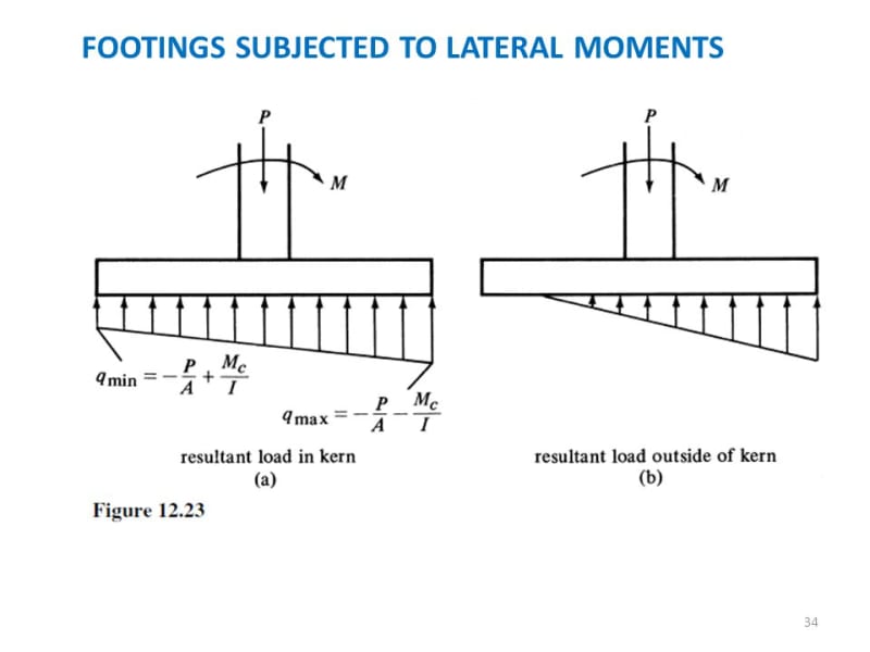
Another way to explain it is that you don't need tension (uplift) restraint to resist moment when you have a net axial compression. This is typically seen in pad footings:
FOOTINGS_SUBJECTED_TO_LATERAL_MOMENTS_obblwt.jpg


centondollar said:
The effective length concept in buckling is related to flexural effects (bifurcation buckling characterized by sudden lateral movement at a critical load), not axial compression.
Pretty sure classic Euler buckling has axial compression force front and centre:
 
"You don’t. For the baseplate the lift the column has to shorten. The column doesn’t want to shorten, and this provides rotational fixity in the absence of bolts. For certain geometries/slenderness this is sufficient to ..."

Without bolts, the bending of the column will not be restrained at the joint, implying miniscule moment transfer and thus miniscule rotational stiffness. I still do not understand why you talk about axial shortening - the loadcase considered here is not compression, but bending due to incrementally onset buckling.

"Pretty sure classic Euler buckling has axial compression force front and centre:
You are not solving the Euler buckling load when running a non-linear FEA, and the energy considered when deriving the Euler bifurcation buckling formula is bending energy and external load energy, both of which involves only lateral displacement and its derivatives of various orders. In the Euler formula, the rotational stiffness is found in the boundary conditions, which cannot be rigid if you do not restrain the rotation properly by sufficiently stiff beam-plate and plate-concrete detailing.

The topic at hand was rotational restraint, and that has little to do with axial compression and everything to do with preventing the beam from rotating. Without bolts, you cannot prevent the plate from simply lifting off of the concrete (loss of contact) and allowing rotation. Ergo, without bolts, you usually cannot achieve a rigid joint.
 
"That is a false conclusion. centondollar I'm started to be at a loss on how I can explain it more clearly. Because you don't seem to be grasping it. Tomfh was fairly accurate and succinct in hit explanation.

Another way to explain it is that you don't need tension (uplift) restraint to resist moment when you have a net axial compression. This is typically seen in pad footings:"

Presumably, your free body diagram is of the plate-concrete interface. In that case, consider that there is only partial contact on a plate without bolts. In such a situation, how do you envision the rotational fixity to manifest? Without bolts creating a force couple (compressive bearing of plate and bolts against concrete, tension in bolts on the side with contact loss), there is no moment transfer and thus no rotational fixity.

The pad footing does not work as an analogy, because that is related to overturning and allowable pressures - not restraining rotation.

PS. The footing case (in its basic form, applied to a footing) involves calculating the stress below the footing with basic beam theory formulas. It has nothing to do with moment transfer from beam-->base plate --> bolts --> footing and the detailing required to obtain such moment transfer.
 
Status
Not open for further replies.

Part and Inventory Search

Sponsor