Continue to Site

Eng-Tips is the largest engineering community on the Internet

Intelligent Work Forums for Engineering Professionals

  • Congratulations KootK on being selected by the Eng-Tips community for having the most helpful posts in the forums last week. Way to Go!

Double 3-Sided Roof Diaphragm 7

StrEng007

Structural
Aug 22, 2014
510
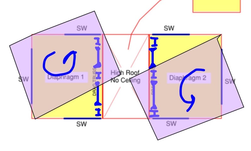
I have a building that features s pop up roof section. Please see the image below.
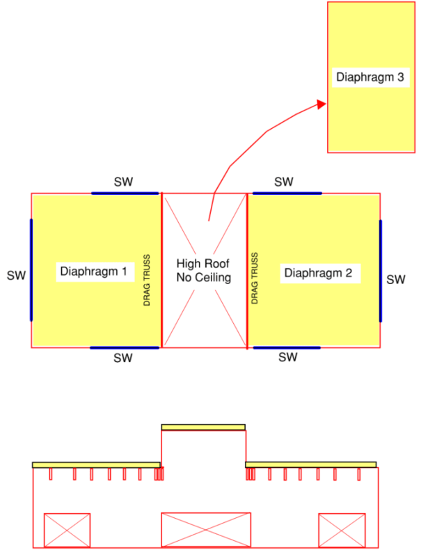
Screenshot_2024-10-07_152347_jihc18.png


Long story short, I have a hole right in the middle of my roof diaphragm. Based on the shear wall layout, there is no vertical element to support the edges of the roof diaphragm shown as #1 and #2.
Would this be a candidate for each diaphragm to be treated as an "open front diaphragm"?

In all the design examples I've seen, the open front end of the diaphragm didn't have an additional "point load" in the transverse direction.

Additionally, what I'm not showing is the fact this roof is a gable. I've shown it as being flat because that helps me first get an understanding of the approach I want to take. My second concern here is being able to get a 3 sided diaphragm to work as a gable roof with a steep slope.
 
Replies continue below

Recommended for you

Isn't your drag truss completing the load path? So you do in fact have 4 sides to your roof diaphragm?
 
I think what your concern is is that each half of the roof acts as an independent building under wind load from the bottom or top of the page with the shear centres towards the outsides and the load centre towards the insides so you will get some diaphragm twist to be taken out by the top and bottom pairs of shear walls. That shouldn't be a problem if the diaphragms are relatively square as shown.
 
Your drag truss looks to be completing the load path for the diaphragm, however, where is the drag taking the lateral load to? Do we have a shear wall system on each side going into and out of the page that you are resolving the load into?
 
human909,
True. But my understanding is that I'll still end up with a 3 sided diaphragm. Even though there is a boundary element at the drag, it doesn't have any positive means to attach to any vertical part of the lateral force resisting system. So I don't see how it's any different that a building that has an open front. At the front of such buildings you don't leave the diaphragm completely "unattached" to anything.

phuduhudu,
In order to accomplish what you're saying, I have to treat the diaphragm as being rigid? I'm not sure how to achieve what you're suggesting.
 
ChorasDen said:
Do we have a shear wall system on each side going into and out of the page that you are resolving the load into?
No, I don't. This is exactly my point.
 
I don't think you actually need a drag strut there. But, yes, I can see designing it as two, 3-sided buildings assuming the aspect ratios work out.
 
To address the question in the OP regarding the offset shear walls inducing lateral load at end of 3-sided diaphragm: you can fairly easily model this conceptually and account for it in your design, biggest issues will be drift at the unsupported side of the cantilever, determination of location where blocking will be required, and ensuring the perpendicular walls are designed for the additional torsional shear they will resist.

Not sure what controls your design, but I'd suggest checking for accidental torsion effects regardless of the lateral load type, whether seismic or wind.
 
ChorasDen said:
determination of location where blocking will be required
Can you elaborate? I'm in a high wind region and the diaphragm will be fully blocked (ends and continuous panel edges) and blocked along the roof boundary (fully blocked between truss ends).

I've got Malone's book that has a section on open diaphragms. It's seems like there are two precursors to it, first make sure the open side is less than 25ft long. Second, make sure your aspect ratio is less than or equal to 1 for a one-story structure. I can meet those requirements.

What's different in my scenario is the "extra" loading that results at the shear walls that frame the pop-up roof. Malone's examples don't have that additional "point load" along the open end of the diaphragm. This is what I was asking in my OP... if that is acceptable.
 
35ft is the allowable L' length in SDPWS, and the allowable aspect ratio is 1.5, check section 4.2.5.2.

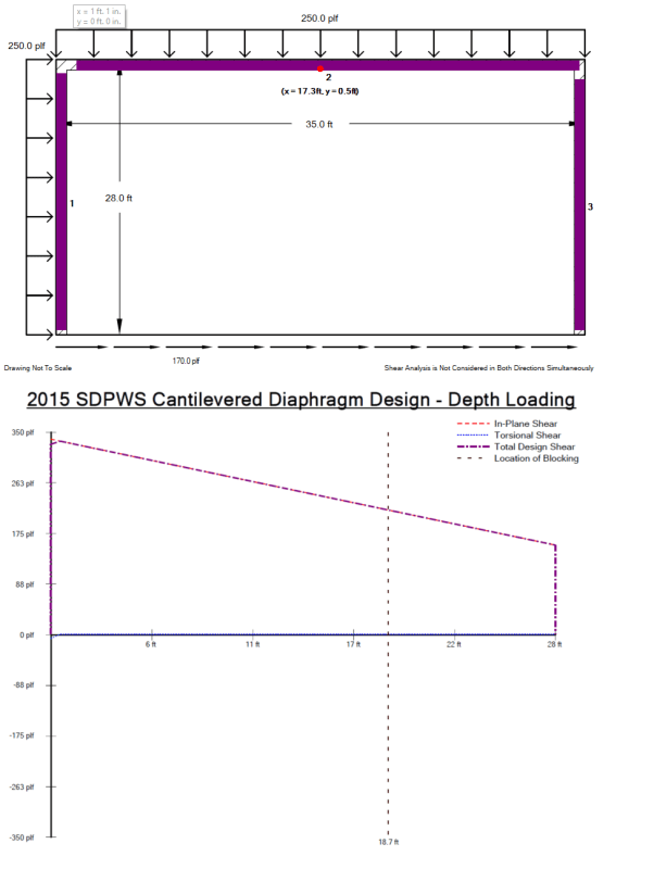
I've shared photos like this on this forum below, but here is a real quick sketch-up showing where blocking would be required. Keep in mind this is for seismic design, not wind, so your allowable design values will differ. You can see the location shown where blocking is required as a vertical dotted line, left side of line has diaphragm shears high enough to require blocking, right side can remain unblocked. If this is a relatively small project, it may be fine to block the entire diaphragm, but on larger jobs, it can be economical to reduce blocking to only the parts of the diaphragm that require it.

As stated, check your walls for torsional shear, it can get quite high, particularly with the additional line load at the end of the cantilever.

Diaphragm2_mii0ss.png
 
Another question is, with an 8:12 roof pitch, can I justify this diaphragm will be rigid enough to support a 3-sided diaphragm. I have never quite understood the behavior of a sloped gable diaphragm, let alone one with such a steep angle.

I had an entire post dedicated to the subject once and had determined that every truss has to act as a "drag support" due to the fact that the shear plane of the diaphragm to truss connection had two orthogonal directions (the angle of the roof being the resultant). I had to just accepted the approach listed by the SDPWS.

 
I'll be honest and say I have not dug that deep into steep roof design, but I think a member on these forums (pham or Kootk maybe?) likes to include the attachment here whenever this question comes up, discussing folding plates. I've never taken the time to read through the attachment, but I've saved it in the hope that I will read it one of these days.

I've always viewed gable ends similar to 2-ply studs at abutting panel edges or 2-ply joists in designed diaphragms, the shear is simply transferred across the gravity supporting member through the panel edge nailing, I'll be honest and say I haven't thought any more deeply on the topic, but always interested to see how others approach it.
 
 https://files.engineering.com/getfile.aspx?folder=05c011eb-0555-4b13-9019-5bd2c8259b18&file=Report_121_-_Plywood_Folded_Plates-1.pdf
I agree with others that drift may be the driver here. Ensuring that the stiffness of each 3-sided area is sufficient so that the non-lateral load resisting framing in the high bay center area doesn't get pushed/pulled/twisted would be my top priority. Design of the "drag truss" and its connections for the extra lateral load and corresponding vertical tension/compression to bring lateral load down from the high roof is another critical component.
 
Yeah, this is a candidate for the double storefront thing so long as you keep diaphragm deflection small enough. The load path is certainly there.

That said, I think that it's a better candidate for moment frames etc on the storefront sides. I fear a diaphragm motion pattern like that shown below which might damage finishes or, in the extreme, destabilize the support of the popup bit.

I usually save the double storefront thing for buildings with lots of lateral load path redundancy where I expect the diaphragms to behave fairly continuously regardless of my weird design approach. Here, things look wide open and, like you said, you've got the pop up acting like a concentrated load / stability demand at the free side of the three sided diaphragms.

On the plus side, if your EW shear walls are as generous as you shown them, deflection control might not be that difficult.

What's the window situation going to be like on the four sides of the popup?

c01_btrf4h.jpg
 
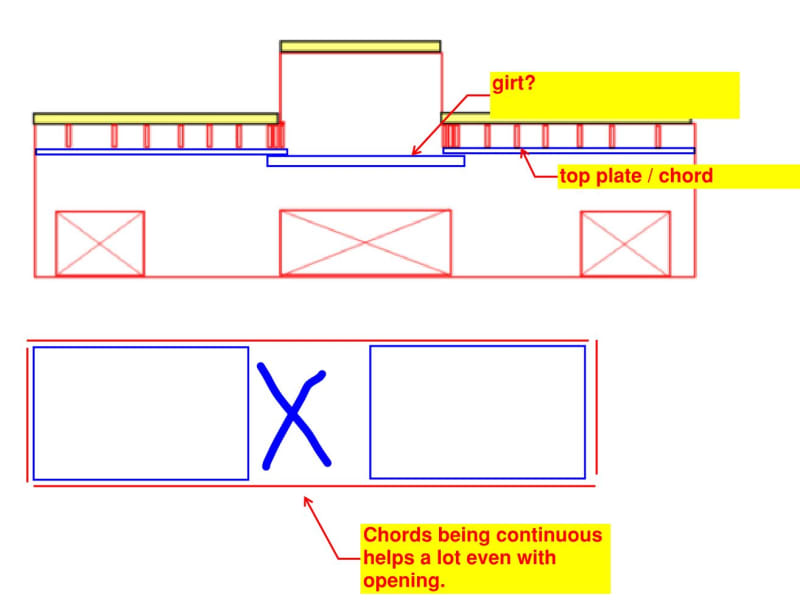
This could be another option. If you'll need girts as shown below anyhow, you could strap your low roof chords to those girts such that the chords can be continuous across the entire building. Then, ideally, you detail the popup to be able to transfer a small amount of shear up and across. In my opinion, restoring chord continuity helps a lot with overall continuity, even with the popup in play.

c01_n9sxjd.jpg
 
I'm leaning towards the introduction of braced wall lines adjacent to the missing part of my diaphragm. I'll be utilizing a true drag truss at these locations to keep the two separate diaphragms simple.
 
ChorasDen said:
I've never taken the time to read through the attachment, but I've saved it in the hope that I will read it one of these days.

I began reading it today, and I can't say that I agree with one of the main concepts it uses which is likely the point of the whole document (i.e. to design a true folded plate).

I suppose it's due to the lack of structural ridge beam, but the document suggests that loading at the ridge lends to thrust and is taken out through the vertical plane of the diaphragm and resolved to the end walls. My understanding in how structures really perform is, if this thrust is present then it's likely the ridge is deflecting. This just doesn't see acceptable to me when we can easily use a collar/rafter tie or a structural ridge beam to alleviate this problem.

So, for the hour that I spent reading the document, I haven't come away with any more insight on how our traditional gable diaphragms work.

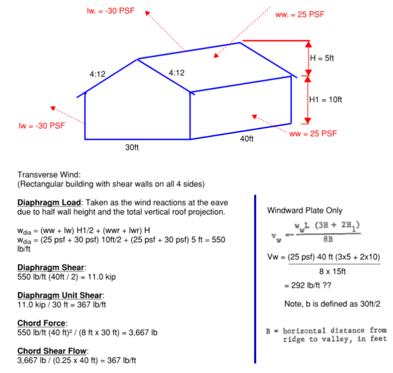
They provided this formula for wind shear, but I don't quite understand it.

Screenshot_2024-10-08_175912_lyc01r.png

_______________________________________________________________________________________________________________________________________________

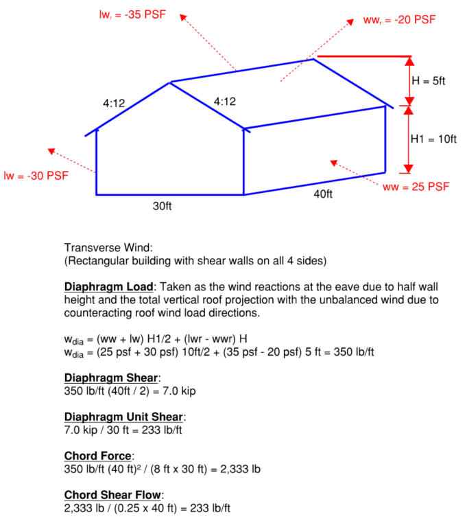
[highlight #FCE94F]I've worked out a scenario for a roof diaphragm where the entire roof acts as one unit. The calculation of the "windward plate" is shown for comparison:[/highlight]

Note in the example below, I chose a windward roof pressure and leeward roof pressure that contribute to the same overall direction.

Screenshot_2024-10-08_221801_pikxfy.png


[highlight #FCE94F]For completeness, I did the same scenario for wind loading that represents a more typical scenario where the windward roof and leeward roof are in opposing directions. I'm providing this to also get your opinion on it.[/highlight]

Screenshot_2024-10-08_221822_rnaus9.png


What I've attempted to understand here is HOW we assume these two planes act together. What really trips me up is that I think the proper way to handle the 1/2 projected wall height is to take the lateral load coming from the wall, and find the vector that pushes load into the plane of the diaphragm.

If you were to only consider the windward wall from either example above, treating the plane of the roof as a two-force member:
(25 PSF x 5 ft) / cos (18.43°) = 131.75 lb/ft (in lieu of 125 lb/ft)
This would give you a load that travelled parallel to the plane of the roof.

The other force component would act vertically down on the projected horizontal plane of the roof:
131.75 x sin (18.43°) = 41.65 lb/ft (Vertical Y)

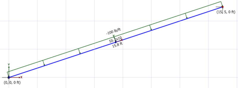
Now for the wind that is normal to the roof (i.e. roof wind load), I understand there is no axial force in the plane of the roof due to wind (therefore you cannot say that wind is pushing parallel into the plane of the roof). But based on the vertical projection of the roof, there is a lateral reaction at the eave and ridge. You can solve that with a FBD, but I don't understand the mechanism behind how the diaphragm "feels" this shear load transfer in the plane of the roof since the wind component is normal to the roof.

Linear load normal to the plane of the roof (represents wind load)
Screenshot_2024-10-08_231710_eyz1ac.png


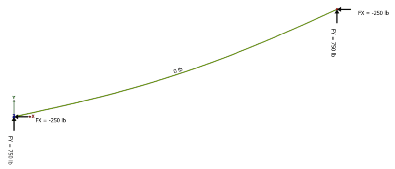
Axial load and reactions at the eave and ridge:
Note there is no axial which to me would have been the force parallel to the plane of the roof. Yet statics has to be in equilibrium so we have overall horizontal reactions.
Screenshot_2024-10-08_231756_u1ufb0.png


I hope I've explained my confusion well enough and that I haven't ended up losing any credit points in the process. I return to this question every couple years and end up just accepting normal practice because it's become so time consuming. But there has to be an explanation that I'm not seeing.

KootK, I know we've discussed ad nauseam and you mentioned the accounting is so involved most probably move past it. Sorry to re-hash old discussions.

I know that some of you understand the time commitment to just ask the question in the first place (examples, images, descriptions, etc.) I wouldn't be doing this if I didn't feel the need to get this one solved.
 
StrEng007 said:
I return to this question every couple years and end up just accepting normal practice because it's become so time consuming. But there has to be an explanation that I'm not seeing.

You've been following the White Rabbit my friend. I believe that I have answers that you seek. However, once you take the red pill, there will be no returning to blissful ignorance. You won't be able to unsee the truths that you've been shown.

The folded plate thing was gifted to us by phamENG. It's appropriate in the contexts that pham usually offers it up but it's a red herring here as it really speaks to utilizing diaphragms to carry out of plane loads whereas your confusion relates primarily to how they deal with in plane loads.

c01_w5zfac.jpg
 
Levity aside, your two statements below represent epically good questions about fundamental diaphragm behavior. I've struggled with this mightily myself.

Frankly, for ridge board systems, I very much doubt that the two planes actually do act together. A ceiling tie (truss) is probably the most convincing system with respect to load sharing. Ridge beams systems likely fall somewhere in between depending on their stiffness. I feel that everything is down to how much vertical restraint is provided to the pitch break.

Anyhow, I think that this is something we can, and should work through. I'm seeing a process that looks like this:

1) I show you some stuff, mostly sketches.

2) You let me know if you're "feeling" what I'm laying down, much like a diaphragm does.

3) I show you some more stuff. We rinse and repeat until you tell me that you've had your "aha" moment and we can stop.

I could see this taking at least three rounds. So maybe a week or two of slow back and forth.

Red pill?

StrEng007 said:
What I've attempted to understand here is HOW we assume these two planes act together.

StrEng007 said:
You can solve that with a FBD, but I don't understand the mechanism behind how the diaphragm "feels" this shear load transfer in the plane of the roof since the wind component is normal to the roof.
 
KootK said:
I could see this taking at least three rounds. So maybe a week or two of slow back and forth.
Time to start another post on the subject?
 

Part and Inventory Search

Sponsor