Tomfh
Structural
- Feb 27, 2005
- 3,584
Follow along with the video below to see how to install our site as a web app on your home screen.
Note: This feature may not be available in some browsers.
TugboatEng said:I didn't know the foreign mariners would have union representation.
TugboatEng (Marine/Ocean) said:I wonder if the thrusters were on the HV or LV switchboards. A ship this size can have up to 3MW of bow thrusters power and sometimes up to 2MW of stern thruster power (this case is not very common).
TugboatEng (Marine/Ocean) said:I was assuming thrusters were on the HV board, the ship has generation capacity of over 12MW. I would expect the LV switchboards to have a rating of half that or less. So the transformer would have a rating of 3-6MVA. Faults during split bus conditions could exceed that rating as the LV bus would be supplying power to the faulted HV bus.
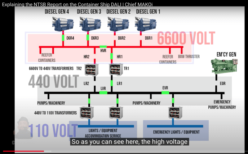
NTSB Report said:The ship’s electrical power was supplied by four alternating current generators,
which were each driven by a diesel engine. Generator nos. 1 and 4 were rated for
4,400 kW, and generator nos. 2 and 3 were rated for 4,000 kW. The generators were
connected to a 6,600-volt high-voltage (HV) main electrical bus by the vessel’s power
management system (see figure 3) that powered various shipboard equipment,
including the main engine lubricating oil pumps, the bow thruster (a propulsor on the
ship’s bow that that assists with ship maneuverability), and reefer containers
(refrigerated containers that cool temperature-sensitive cargo).3 The HV main
electrical bus could be split with an installed main bus tie (HVR in figure 5 on page
88), which would isolate two generators on each side of the bus. The bus was
designed to be normally operated in a closed-bus configuration (meaning the main
bus tie, which connected the two sides of the bus, was closed); this was the case
during the accident voyage.
A 440-volt low-voltage (LV) electrical bus was connected to the HV bus via
redundant step-down transformers (TR1 and TR2 in figure 5). The LV bus powered
vessel lighting and other equipment, including steering gear pumps and the main
engine cooling water pumps. Breakers were located on either side of the step-down
transformers—HR1 and HR2 on the HV side, LR1 and LR2 on the LV side. The LV bus
could also be split with an installed bus tie (LVR in figure 5). The bus was designed to
be normally operated with the LV bus tie closed, which was the configuration during
the accident voyage. With the LV bus tie closed, one transformer (TR1 or TR2) is
designed to be used, with its associated HR and LR breakers (see figure 5).
Can they freely leave?
![[hairpull3] [hairpull3] [hairpull3]](/data/assets/smilies/hairpull3.gif) They both have their own dedicated 20 amp 115V circuits now, in addition to old daisy chained 15amp circuit.
They both have their own dedicated 20 amp 115V circuits now, in addition to old daisy chained 15amp circuit.
