Eng-Tips is the largest engineering community on the Internet

Intelligent Work Forums for Engineering Professionals

Baltimore Bridge collapse after ship collision 125

Replies continue below

Recommended for you

John, phones may have been seized for evidence but have they not been returned or replaced? A simple imaging of the phone is all that is necessary for evidence. The crew may have access to launches if the company provides them and their credentials allow them to go ashore. Ships at anchor will periodically hire launches. This ship is essentially at anchor.

Nukeman, I am making a few assumptions. Ships I have sailed on has been serviced by a 480V switchboard. These are usually capable of supplying a few MW of power, say 2-5. These were ships without thrusters. This ship has the 6.6MV switchboard. I wonder if the thrusters were on the HV or LV switchboards. A ship this size can have up to 3MW of bow thrusters power and sometimes up to 2MW of stern thruster power (this case is not very common).

I was assuming thrusters were on the HV board, the ship has generation capacity of over 12MW. I would expect the LV switchboards to have a rating of half that or less. So the transformer would have a rating of 3-6MVA. Faults during split bus conditions could exceed that rating as the LV bus would be supplying power to the faulted HV bus.
 
I didn't know the foreign mariners would have union representation. I think the individual in 3DDave's video is lying about some details with regards to representation as he is a union rep and is trying to sell his position.
 
its the same with airline crew that have issue in the USA.

The USA unions claim they are doing things and representing them. But in reality its a media tick in the box and in some ways they will work against them.

Basically the unions would like to ban all none members from ever entering the country working and only have USA company's doing it with union workers.
 
[quote="trapped" seems a bit inflammatory and click-baity][/quote]

Can they freely leave?

-----*****-----
So strange to see the singularity approaching while the entire planet is rapidly turning into a hellscape. -John Coates

-Dik
 

Some of them are among the lowest paid people on earth. There was a recent situation in the UK where they were paid a little over a couple of pounds per hour for exceptionally long hours.


-----*****-----
So strange to see the singularity approaching while the entire planet is rapidly turning into a hellscape. -John Coates

-Dik
 
TugboatEng (Marine/Ocean) said:
I wonder if the thrusters were on the HV or LV switchboards. A ship this size can have up to 3MW of bow thrusters power and sometimes up to 2MW of stern thruster power (this case is not very common).

The one line diagram clearly shows the one bow thruster was connected to the HV bus and it was 3000KW. There were no other thrusters.

TugboatEng (Marine/Ocean) said:
I was assuming thrusters were on the HV board, the ship has generation capacity of over 12MW. I would expect the LV switchboards to have a rating of half that or less. So the transformer would have a rating of 3-6MVA. Faults during split bus conditions could exceed that rating as the LV bus would be supplying power to the faulted HV bus.

NTSB Report said:
The ship’s electrical power was supplied by four alternating current generators,
which were each driven by a diesel engine. Generator nos. 1 and 4 were rated for
4,400 kW, and generator nos. 2 and 3 were rated for 4,000 kW. The generators were
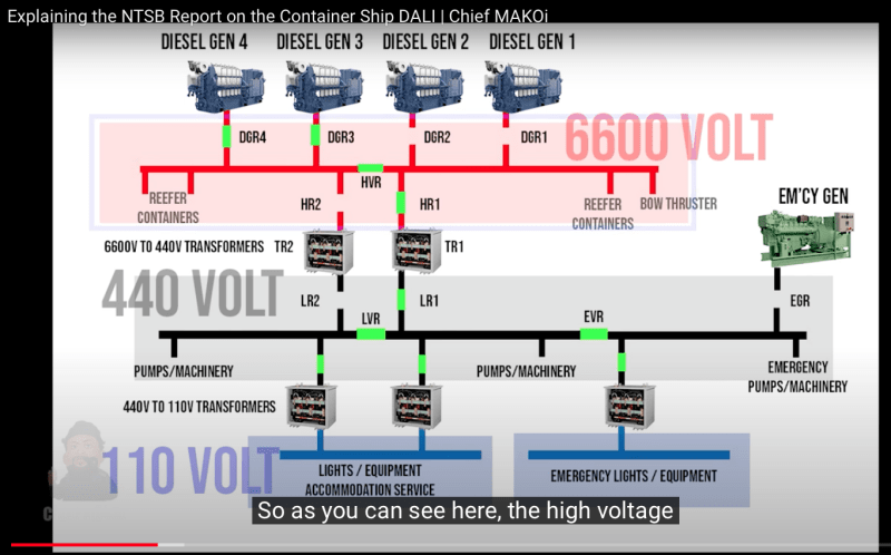
connected to a 6,600-volt high-voltage (HV) main electrical bus by the vessel’s power
management system (see figure 3) that powered various shipboard equipment,
including the main engine lubricating oil pumps, the bow thruster (a propulsor on the
ship’s bow that that assists with ship maneuverability), and reefer containers
(refrigerated containers that cool temperature-sensitive cargo).3 The HV main
electrical bus could be split with an installed main bus tie (HVR in figure 5 on page
88), which would isolate two generators on each side of the bus. The bus was
designed to be normally operated in a closed-bus configuration (meaning the main
bus tie, which connected the two sides of the bus, was closed); this was the case
during the accident voyage.

A 440-volt low-voltage (LV) electrical bus was connected to the HV bus via
redundant step-down transformers (TR1 and TR2 in figure 5). The LV bus powered
vessel lighting and other equipment, including steering gear pumps and the main
engine cooling water pumps. Breakers were located on either side of the step-down
transformers—HR1 and HR2 on the HV side, LR1 and LR2 on the LV side. The LV bus
could also be split with an installed bus tie (LVR in figure 5). The bus was designed to
be normally operated with the LV bus tie closed, which was the configuration during
the accident voyage. With the LV bus tie closed, one transformer (TR1 or TR2) is
designed to be used, with its associated HR and LR breakers (see figure 5).

It appears that the LV bus didn't carry a very large load as a percentage of the total.

Continuing the theme of assumptions and wild speculation, I would expect that HV loads (not including the bow thruster) would be somewhat balanced on either side of the tie breaker (HVR) and should that breaker ever open with both transformers in service, there would be more than enough load on one half of the HV bus to trip at least one of the six breakers that the power would need to flow through to get to the dead side of the HV bus. A fault on that side would only make it trip faster and any backfeed from the LV bus to the HV bus will be very short lived.

Edit to speculate: Perhaps this potential scenario is the reason they only use one transformer at a time, to limit the chance of HVR opening and causing the loss of power to the LV bus as well.

[sub]
[/sub]​
 
I should clarify that a ship's compliment consist of officers and crew. The officers, typically 10, are in a union. The rest of the crew are likely not. Also, don't forget the ship had maintenance riders on board as well. I see no reason the maintenance riders should be required to remain, who knows if they did.

Edited for clarity.
 
Agree with Nuke's post above. The NTSB simplified power distribution flow diagram does NOT show any of the control functions associated with the power distribution system nor interdependencies.

From a design and operational standpoint, it does seem like a poor design choice to have a some of the functions required for propulsion and steering to be hung off a different buss. In a perfect world, you would think propulsion and steering being critical items, would perhaps be on their own isolated buss(es) to prevent refrigeration or other ship loads being cause of tripping a main breaker that shuts down the ability to control the ship?

Reminds me of how electricians like to daisy chain outlets across multiple rooms in a house, thus when breaker trips in one room, it also effects other rooms in house. The thinking being that all rooms would not be used and loaded at same time.

Well my current house had the main floor master bathroom sink/mirror outlet fed by same 15 amp circuit as the upstairs bathroom sink/mirror outlet. Then when folks in each bathroom try to use a blow driers at same time, on two different floors.............[hairpull3] They both have their own dedicated 20 amp 115V circuits now, in addition to old daisy chained 15amp circuit.


I had forgotten about the possibility of the bus tie opening up, splitting the transformers between two separate sources.... (it was late/I was tired....)

But, I would also assume that the ship's automation could handle a situation where if the bus tie opened, it could simultaneously trip off one of the two transformers to prevent a mismatch and/or backfeeding. (my only question would be speed--could it trip fast enough (like within less than 1/2 cycle of the bust tie opening) to prevent problems? Of course not sure if that would be acceptable because an automation failure could cause a dangerous situation, too, if it did not trip the transformer when the bus tie opened.
 
To note there maybe human interaction outside the OEMs procedures and other technical faults which has ment the crew has bastardised things to continue to sail long term.

I suspect there are issues which we don't know about. And the crew are operating outside the manual.
 
There was a time when the Government led the way with technology development. Mission to the moon is a great example, led by NASA.

However, today the opposite is true. The screen shot from Chief Makoi's presentation is a prime example of how private industry leads the government today in terms of technology development, and with skilled employees.

Edit: I doubt reefer containers run directly off 6600 Volt Buss. I would assume the voltage is stepped down to feed reefer's.........

Quick Google says this:

"Reefer containers operate on 460/480 volts (V), 3 phases
The units can run on 50 or 60Hz
The power supply should be grounded with a 30 amp minimum circuit breaker. The 460V machinery main circuit breaker will trip at 29 amps"

Perhaps 5 years from now, this event will be known as "The Dali-Rig" ?

Power_jkw75c.png
 
I was waiting for Chief Makoi's video... He's great at explaining these things.

So based on his video plus some comments that his viewers made (and he responded to), I'm thinking:

[ul]
[li]Some sort of fault occurred in TR1 (I speculated on this before), leading to LR1 and HR1 opening. In the comments, someone mentioned the possibility of an insulation fault on TR1 (Chief Makoi responded saying that was a distinct possibility.[/li]
[li]This killed the 440v bus, the water/oil/fuel pumps for the main engine, leading to engine shutdown.[/li]
[li]This ALSO killed the fuel pumps for DG3 and DG4.[/li]
[li]Due to the lack of much load on DG3/4 after the TR1 trip, not very much fuel was required to keep the DG's running. So they continued to operate. As he stated, it could be the remaining pressure in the fuel lines and/or gravity feeding that allowed enough fuel for them to continue without operational fuel pumps.[/li]
[li]There is some lack of clarity as to exactly how long it took for the EDG to come online (of course, it would NOT be instantaneous)[/li]
[li]The crew manually restored TR1, putting load back on DG3/DG4[/li]
[li]Speculation: For some reason, the fuel pumps for DG3/4 did NOT come back online when the 440v bus was restored (why?) This lead to fuel starvation, which caused the black smoke.[/li]
[li]Eventually fuel starvation become so bad that DG3/4 tripped, leading to the 2nd blackout.[/li]
[li]By this time EDG was online, so the nav lights stayed on.[/li]
[li]DG2 came online and took over, ending the 2nd blackout. It was not mentioned if TR1 had to be manually restored a 2nd time here.[/li]
[/ul]

During all of this, there simply was not enough time to restore the aux systems required to restart the main engine. From the simulations I mentioned above, there are several (probably manual) steps in starting the main engine, so it would have been a race to get the engine started, complicated by the 2nd power failure.

Another question I have: in the simulators, generally only ONE of the DG's has it's aux systems (including the fuel pumps) connected to the EDG for starting. Which one is it here? (It was not mentioned in the NTSB report). I'm guessing it was DG2 because it was able to come online during the 2nd blackout. THIS also begs the question: During the 1st blackout, why did DG2 not automatically start once the EDG was running? Leading back to how long did it take for EDG to come online? Again, simply not enough time for all of the steps to occur? Or a problem with the automation?


Roga50, If DGR3 and 4 are still running and their breakers closed, then HVR buss would have power, and I would not expect DGR2 to come on automatically, until HVR buss looses power.

The other factor could be some of the automation was bypassed as a "Dali-Rig" to keep going, and defer needed repairs till they are back in home port?
 
I think the issue here that may have been missed by the automation is that DG3/4 fuel pump (and probably also cooling pumps, at least per the simulators I've been looking at) would not have been powered by the 6600v bus.

So when those pumps lost power, the automation SHOULD (if I had designed it, at least) have started the DG that had aux pumps powered by the EDG bus (once the EDG came online). Or, automation saw the problem but had no alternatives because DG2 could not start yet.

The important part here though is that if the EDG did not get running in time, it is possible that DG3/4 was actually put back under load, without fuel pumps and tripped offline before EDG and (and subsequently, DG2) could come online. So that makes the exact timing of when EDG came online become an important piece of the puzzle.

So look at it like this (revised a bit):
[ul]
[li]TR1 trip occurs[/li]
[li]Due to the lack of much load on DG3/4 after the TR1 trip, not very much fuel was required to keep the DG's running. So they continued to operate. As he stated, it could be the remaining pressure in the fuel lines and/or gravity feeding that allowed enough fuel for them to continue without operational fuel pumps.[/li]
[li]The crew manually restored TR1, putting load back on DG3/DG4[/li]
[li]Speculation: For some reason, the fuel pumps for DG3/4 did NOT come back online when the 440v bus was restored (why?) This lead to fuel starvation, which caused the black smoke.[/li]
[li]Sometime around here, EDG comes online. A bit before DG3/4 tripped, but because EDG doesn't power the pumps for DG3/4, it is of no assistance to them.[/li]
[li]Eventually fuel starvation become so bad that DG3/4 tripped, leading to the 2nd blackout.[/li]
[li]Nav lights stay on because they are powered by EDG, which by this time is running.[/li]
[li]With it's pumps being powered by EDG, DG2 now starts and takes the load, ending the 2nd blackout. It is possible that automation saw the pump issue on DG3/4 and DG2 even began to start before DG3/4 tripped, but there would be time required for it to get up to speed and synchronize with the 6600v bus before it's breaker could close.[/li]
[/ul]
So the question becomes: if EDG was actually running (it seems that it was, because the Nav lights stayed on for the 2nd blackout) before DG3/4 tripped, was the automation set up to detect no aux pumps running for DG3/4 and automatically start DG2 prior to DG3/4 finally tripping from fuel starvation? Or was there just not enough time here?

2nd question: why did the DG3/4 fuel pumps not come back up with the 440v bus, or did they, but it was too late by then?

These questions should all be easier to answer once they publish the Alarm Monitoring System logs, which should show the exact sequence of events of each trip and sensor.

 
The NTSB report says that the EDG started during the first blackout and was already running during the second. On loss of power the emergency switchboard bus tie breaker opens, the EDG starts and the EDG breaker closes. It takes the chief engineer with a key to physically go to the emergency switchboard (usually located high in the house) to close the emergency switchboard bus tie breaker to connect the emergency switchboard to the main bus. This could not have occurred within the timeline of events.
 
Back
Top