Continue to Site

Eng-Tips is the largest engineering community on the Internet

Intelligent Work Forums for Engineering Professionals

  • Congratulations waross on being selected by the Eng-Tips community for having the most helpful posts in the forums last week. Way to Go!

Beam connection stability 7

Status
Not open for further replies.

Vrpps EIT

Structural
Aug 21, 2018
58
CA
Hi All,

Attached the situation in the pic, under this loading, when the overhang portion has a column on top of it and has a point load. This creates a moment at the beam and column-A connection. which in turn will create an uplift load. So, this uplift will be resisted by the beam & column-B connection at end of the beam which is fixed there or the four bolts that are connected at beam column-A connection? Or in simple terms what tensile force should the 4 bolts at column support A near the overhang to be checked for is it the reaction force that support will carry?
I can see it as a tower crane with balancing counter jib but I am missing something here.

Thank you for your time!
 
 https://files.engineering.com/getfile.aspx?folder=2e3d4853-5d88-4ea1-a52b-861a35338f7a&file=Scan001_(5).jpg
Replies continue below

Recommended for you

Like human909 said, check you don’t bend your columns.
 
If I consider the entire bending moment to be transferred there at that junction into the column then the column fails in its bending capacity, so that's why asked should that moment be 50% or full?
 
Vrapps EIT,

If you transfer moment from the beam to column, the amount of moment put into the column is dependent on the flexural stiffness of both the column and the beam (i.e., an indeterminate system). That is, if your beam is much stiffer than your column, your column will not pick up much moment. If your column is much stiffer than your beam, it will pick up more of the moment.
 
Agree with winelandv - the moment from the cantilever and point load comes into the joint at the top of your column and distributes out to the beam and column relative to their EI values and lengths.
This takes an analysis, not a direct answer like 50-50 or 40-60.

You could take a bracketed parametric approach and assume 90% to the column....design the column...then assume 90% to the beam, and design the beam.
Very conservative but if you don't have the ability to perform a direct analysis then that would be one approach.


Wouldn't it also be dependent on the stiffness of the plate? A guy can really turn this into a science experiment which is why I tend to design these as pin supports with a relatively thin plate. I seem to recall a connection example very similar to this in an AISC design example PDF. IIRC they didn't design for any moment transfer.

Of course if you are using very slender elements and toeing the line on design, assuming no moment transfer is potentially asking for trouble.
 
@Vrpps_EIT:

1) What size is your beam?
2) What size is your column?
3) How tall is your column?

Let's put some numbers to this for sport, if nothing else.

Assuming a rigid beam to column connection will allow you to very simply put an upper bound number to the share of the incoming joint moment that will be resisted by the column as follows:

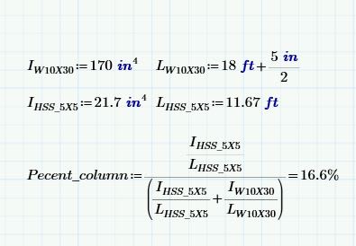
% = 100 x (I_col/L_col)/(I_col/L_col + I_beam/L_beam)

That assumes that both member are still and pinned at their far ends.
 
Rabbit12 said:
Wouldn't it also be dependent on the stiffness of the plate? A guy can really turn this into a science experiment which is why I tend to design these as pin supports with a relatively thin plate.

It most definitely would. It would be dependent upon:

1) The flexibility of the cap plate including prying action;

2) The flexibility of the bolts including prying action;

3) The flexibility of the beam flange including prying action;

4) The impact of axial load effectively prestressing the joint;

5) The impact of any bolt pretension effectively prestressing the joint;

5) The fact that the apparent flexural stiffness of member decreases with increasing axial compressive load.

So, yeah, a science experiment indeed.
 
Above, a couple of real world examples were mentioned wherein ignoring incidental moment transfer into columns caused -- or may have caused -- problems. Both examples share a commonality: insufficient beam stiffness. And that, I think, points to how a skillful designer ought to tackle these things:

1) Design the beam with enough stiffness relative to the column that moment transfer does not merit explicit checking.

2) If the beam slenderness relative to the column is questionable, then delve into a more detailed analysis to assess the impact of that.

I believe that we bring our skills to bear upon our craft most effectively when we are able to use our finely honed judgments and intuitions regarding structural behavior to allow us to focus on that which is truly important before firing up the fancy math machine. In most, non-slender situations, I would expect that to be this:

dold said:
I'd be more concerned about the stability of the beam itself (is it restrained against rotation along its longitudinal axis). I.e., make sure the column doesn't move 'in and out of the page'.

That just smacks of sound engineering judgment.

As any practicing, production house engineer will tell you: we don't make our money on the things that we check; we make our money on the things that we're able to not check by way using good judgment and intuition. That's the value of experience and a sound, fundamental understanding of structural behavior. Show me a project where absolutely everything got checked... and I'll show you a project that lost a crap ton of money for the firm that took it on. You just can't compete like that in the private sector.
 
When would you say that column bending due to frame action doesn’t warrant checking? I know a guy who was caught out on that one. Columns visibly bent too much due to beam end rotation.

Nothing worse than arguing that yeah it’s visibly bent but that it’s all fine, honest...
 
KootK (Structural)12 May 20 23:30
@Vrpps_EIT:

1) What size is your beam?
2) What size is your column?
3) How tall is your column?

W10x30 beam
5x5x3/8
11'-8"
 
It's situation dependent and I'll know it when I see it. Here, assuming a 10' column:

- W12 or larger over HSS4 or smaller... No check.

- W8 over HSS8... Check, unless I had access to the cant deflection and it was real small.

I'm up for some sport. Throw something at me and I'll call it.

In this particular situation, I would have designed the column for an eccentricity of half it's width at a minimum to reflect the anticipated beam curvature I've the column which would, of course, help some.
 
So this much as an upper bound estimate assuming the connection to be utterly rigid. I'd have designed the column for a minimum moment of about 7.5%.

c01_b1apr5.jpg
 
The moment there is 35kip-feet & supposedly that column has a little more in its capacity there with 50ksi as yield strength
 
Wow! that was a quick way to get the relative rigidity between the members and find out the % of moment transfer to column!
 
Is the column's share of the moment then 35 k-ft or 0.166 x 35 k-ft = 5.81 k-ft? It it's the latter, no problem. If it's the former, I'd be looking for a stiffer beam or looking at a beam-column design for the column as you'd be at at an 88% utilization rate based on bending alone.
 
no the 35kip-feet is the total full (if its 16% of it then its 5.81k-feet)
 
Vrpps,

If you are taking this approach (moment distribution in rigid joint), you have to make sure the beam and the column are rigidly connected, otherwise, the moment distribution will not happen, or result in partial distribution (that nobody knows how much.
 
Status
Not open for further replies.

Part and Inventory Search

Sponsor

Top