Continue to Site

Eng-Tips is the largest engineering community on the Internet

Intelligent Work Forums for Engineering Professionals

  • Congratulations cowski on being selected by the Eng-Tips community for having the most helpful posts in the forums last week. Way to Go!

Bolt axial force. 1

Status
Not open for further replies.

takio

Mechanical
Jul 9, 2019
37
Hello

Capture1_ddadh7.jpg

Capture_df45zc.jpg


Would anyone please help me with this calculation?
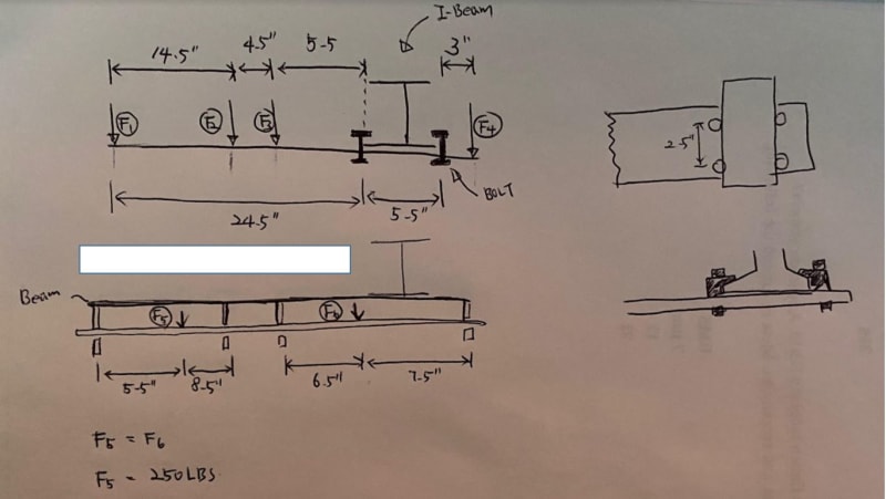
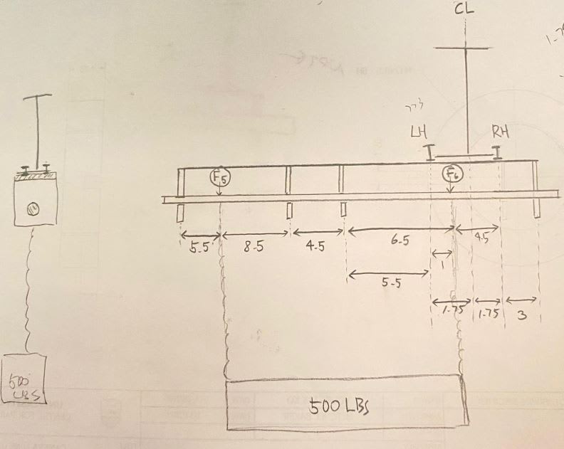
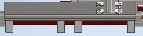
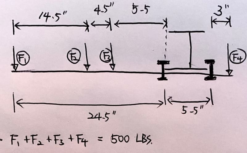
My goal is to know the proper preload for the 4 bolts that hold the I-beam and the beam structure together, using the clamps.
I used 5/8" grade 5 bolts.
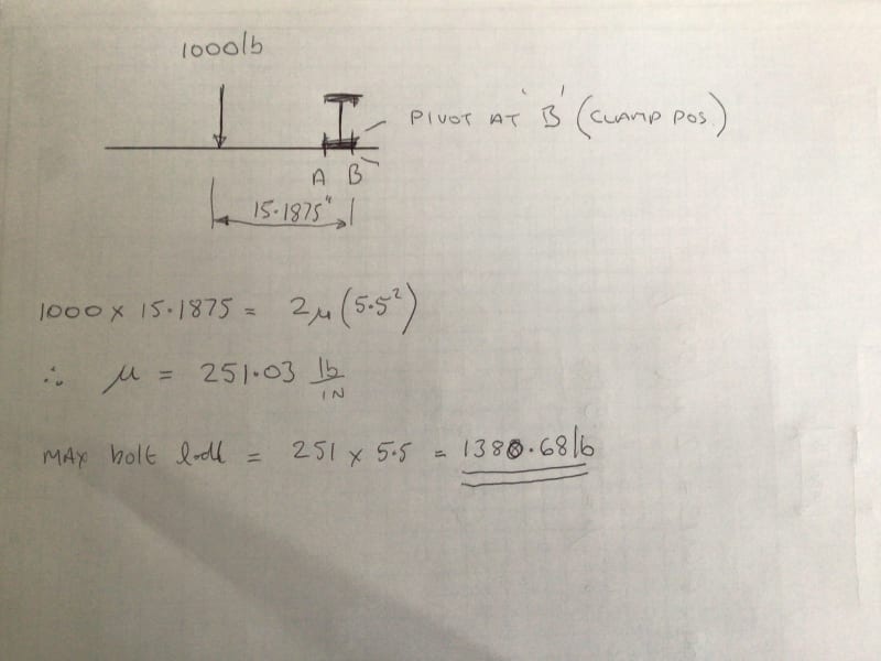
and How to calculate the axial bolt force of the bolts? I ran FEA simulation and I would like to compare the simulation was run properly. so I thought I could compare the hand calculation of axial force to simulation result.
Please let me know if there need to be more information.

Thank you
 
Replies continue below

Recommended for you

Yes, more information is needed. The most obvious is the magnitude of the each of the forces, individually. I'm also having trouble understanding the configuration of the beams and bolt locations. You may need to provide diagrams from additional perspectives to clarify the connection.


Rod Smith, P.E., The artist formerly known as HotRod10
 
yeah, I have very little understanding of the sketch. The four forces are on a transverse beam ? (that's what I get from the little view of the model).

and I think you're asking about the f bolts in the little model sketch, attaching the transverse beam to the central structure ?

the 2 LH bolts react bending from the 3 LH forces, the 2 RH bolts react bending from the RH force.

are you sure the fasteners react the moments with axial loads ? (are the fastener axes aligned with the transverse beam)
It would be more typical if the fasteners carried the moment as shear forces (with the fastener axes out-of-the page).

can you calc a bending moment ?

another day in paradise, or is paradise one day closer ?
 
As a WAG, two 1/2" dia A325 fasteners, unless you have a whole bunch of them. I don't like A307 fasteners for anything other than stair treads.

Rather than think climate change and the corona virus as science, think of it as the wrath of God. Feel any better?

-Dik
 
Hello

Thank you so much for offering your help.
Capture_odrb6b.jpg

so, the beam has 4 blocks with holes to hang a rod. and the rod holds total 500 lbs. the two load locations (f5 and f6) are in between the blocks.

and the beam clamp is BT2G16.
Please let me know if you need more explanation.
I am actually not an engineer, and I have limited knowledge, but I think I could understand your explanation.
Thank you so much for this help again.

Thank you
 
so moment due to F5 (about the middle of the supports, the four bolts) is F5*(8.5+4.5+5.5+5.5/2) = 250*21.25
and F6 is F6*(5.5/2-1) = 250*1.75
so moment is 250*(21.25+1.75)

so the load on each of the LH fasteners is 500/4+250*23/5.5/2 = 648 lbs
and on the RH fasteners 500/4-250*23/11 = -398 lbs (really this will be the rod pushing against the I-beam flange, that the clamps are clamping onto). this will try to loosen the clamps.

so you should have more than 400 lbs preload, depending on your safety factors, and the strength of these clamps should exceed 1100 lbs (conservative).

another day in paradise, or is paradise one day closer ?
 
Hi Youngtaki

According to the link you provided the max safe working load for each bolt is 2219 lbs, so are you worried that you have the wrong size clamps, also on the link it provides the torque 109ft-lbs which you tighten each bolt to with a torque wrench.
I don’t quite understand your last post why is F4 on the other side of the beam.

“Do not worry about your problems with mathematics, I assure you mine are far greater.” Albert Einstein
 
Whereabouts is this detailed used?
If this is the end connection of your cantilever, I don't like the detailing much
You will induce a whole bunch of secondary moment / secondary tension effects with this detail that will be much harder to quantify

Capture_ln7gkw.png
 
Greenalleycat's sketch looks to me to match the detail above..

This is going to put a lot of prying force into the bolts, which severely limits their capacity.

I would suspect you're going to need to preload them to their limits.
 
@swiny, yea I snipped the detail into my post so Taki knew which one I was referring to. Just wanted to give them the chance to clarify if I was misunderstanding.
 
The advice you have received is good advice, but if you are not an engineer and have limited knowledge, you should not be taking on this task.
 
Hello, rb1957

Thank you so much for your answer! and sorry for the late reply.
would you mind letting me know if 5.5/2 is supposed to 2.75? the distance from the middle of I-beam to the bolt.

500/4+250*23/[highlight #A40000]5.5/2[/highlight] = 648 lbs
500/4-250*23/11 = -398 lbs

Thank you
 
Hello MotorCity

I am actually working with an engineer, and I am going to get confirmation, after working on this on my own.
Thank you for your interest.
 
Hi YOUNGTAKI

According to my calculations the preload for each bolt should be 1380.7lbs basing my calculations on the steelwork being rigid and calculating the tension in the bolts based on load offsets.
My first step I found a equivalent resultant load for all the separate loads given and then positioned that load to maintain the resultant moment the structure would experience see diagram below. The bolt preload is within the range of the clamp you have selected however if I was you I would just tighten the clamps to the maximum torque recommended by the clamp supplier.

.
7B23C26E-84ED-417F-81AD-D259727AB45C_iqyyc1.jpg


“Do not worry about your problems with mathematics, I assure you mine are far greater.” Albert Einstein
 
1000 lbs ? ... 2*250 lbs, no? (see post at 17:39 on 25th)

15.1875" ? I get the centroid of the loads being (8.5+4.5+6.5)/2 = 9.75" left of F6
and F6 is 1" to the right of the LH support
so distance to RH support is 9.75-1+5.5 = 14.25" (ok, thought it was more different than that)
and remember two bolts and A and B.

oh, looks like I dropped that ...
moments about RH fasteners ... 250*((8.5+4.5+5.5+5.5)+(5.5-1)) = 250*28.5
load on LH fasteners = 500/4+250*28.5/(5.5*2) = 773 lbs
and RH fasteners = 125-648 = -523 lbs

another day in paradise, or is paradise one day closer ?
 
Hi rb1957
I worked on the basis that there are two 250lb loads and four 125lb loads which is how I got the 1000lb load and then in accordance with my earlier post I calculate the bolt loads using one side of the clamp as the pivot point, the one thing I haven’t included is the 1000lb divided by the number of clamp bolts which means the preload I gave should be increased by 250lb. 👍

“Do not worry about your problems with mathematics, I assure you mine are far greater.” Albert Einstein
 
I think the latter picture is meant to clarify the four forces on the initial post.

but re-reading the later pic, there's a small confusion with the dimensioning ...

the top pic says the overall length is 33",
but the lower pic says 14+4.5+14 = 32.5" ?

it looks like the length of the LH rod ... top 14.5", lower 14"

another day in paradise, or is paradise one day closer ?
 
Hi rb1957

Yes I chose to ignore the dimensional error but it’s what forces are involved because he adds F5 and F6 in a later post which appear to be 250lbs each, if -F5 and F6 are meant to replace F1 to F4 then it’s a different story regarding the loads, maybe the OP will clarify.

“Do not worry about your problems with mathematics, I assure you mine are far greater.” Albert Einstein
 
yeah, he says 500 lbs applied. I figured the first "F1+F2+f3+f4 = 500lbs" was the same as the later "F5 and F6 = 250lbs each", distributed to F1-4.

another day in paradise, or is paradise one day closer ?
 
Hello

I am so sorry for the confusing diagram and dimensions.
I made a better diagram as below.
@Rb1957

From your first approach, I recalculated on my own.
1) Find moment around CL (center line of I-beam)
Moment from F5 : M_F5=250*(8.5+4.5+5.5+2.75)=250*21.25
Moment from F6 : M_F6=250*(1.75)
M_total= M_F5+M_F6=250*(21.25+1.75)=250*23=5750
2) Load_LH
500/4+5750/[highlight #FCE94F]2.75[/highlight]/2=1170
3) Load_RH
500/4-5750/[highlight #FCE94F]2.75[/highlight]/2=-920
Why did you use 5.5 which is distance between two bolts, instead of the distance between bolt and CL?

From your second approach
1) Find moment around RH
250*(8.5+4.5+5.5+5.5)
250*4.5
=250*28.5
2) Load on LH
=250*28.5/5.5/2+500/4=772
3) Load on RH
= ?
I don't understand Load on RH.. Would you mind planning your equation?


@desertfox
Rb1957 explanations are right.
"F1+F2+f3+f4 = 500lbs" was the same as the later "F5 and F6 = 250lbs each", distributed to F1-4"

Thank you


Capture_egkhzt.jpg
 
Status
Not open for further replies.

Part and Inventory Search

Sponsor