Continue to Site

Eng-Tips is the largest engineering community on the Internet

Intelligent Work Forums for Engineering Professionals

  • Congratulations KootK on being selected by the Eng-Tips community for having the most helpful posts in the forums last week. Way to Go!

Can Position Tolerance and Run-Out can be applied together? 2

Status
Not open for further replies.

pandeydhiraj

Mechanical
Dec 3, 2013
5
In any case can Position Tolerance and Run-Out can be applied together to a Feature of Size or plane surface.
I know both are location control doesnot make sense if applied to same feature, but just want to make sure about this thing.
Thanks
Dhiraj
 
Replies continue below

Recommended for you

pandeydhiraj -- Yes, since runout is composed of location, orientation, and form, it can be difficult to separate out one cause from the others. But that's why I proposed that the position tolerance would be smaller: it would control location and orientation, leaving the simple runout check as the form error alone.

However... remember that position will be checking the axis as derived from the "actual mating envelope," and that's why the other portion of this thread is discussing how the roundness errors may or may not factor in to these ideas.
 
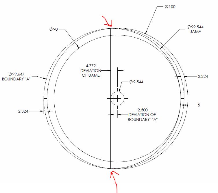
I'm trying to duplicate the math for this in GeoGebra. But I run into the problem that the center point of the inscribed circle as limited by the Dia 100 on the left and the Dia 90 on the right is unaffected by the radius of the arc segment, identified Dia 99.544 and manipulated in the diagram by dragging point D.

See
 
A question about that graphic: What is the dot/axis that is shown as 4.772 to the left? CH labeled it in yellow as the "axis of the cylinder" -- but what cylinder? AME?
 
3DDave,
Could the problem be that you're looking at the inscribed instead of circumscribed circle? My assumption was that this was an external feature so the UAME would be the smallest circumscribed circle which would be coradial with the arc of size 99.544

JP,
I believe that is the center of the UAME which would be a circle/cylinder of diameter 99.544, coradial/coincident with the arc of size 99.544 shown. At least thats what I was going by when I put it in CAD to evaluate pylfrm's initial graphic.
 
CH said:
This is why I will be convinced when I see surface-to-surface comparison.

Sorry, but I'm not sure what kind of comparison you expect to see.
 
3DDave 15 Jan 19 17:54 said:
I considered that, but the largest diameter would be the 99.54 arc diameter, not the chord

A little confused as to why your statement seems to disagree with me when your example is very close (albeit with what looks like slightly less position error) to the one provided by pylfrm, which I supported in my statement? And why you mentioned the chord? Maybe you could explain a little? It seems to me that we actually agree...

Is it because I used the term "smallest" circumscribed circle? I only meant that as in 99.544 is actually the largest diameter arc which still has 180 degree opposed points (anything larger, which while creating more position error, is invalid - including my example of 99.99 in the figure I previously attached has less than 180 degree opposed points) is coradial/coincident with the UAME which is the smallest circumscribed circle which will fit around the feature.

Edit: grammar
 
Struggling probably with the relationship between axis of the UAME and the applicable surface (RFS case) of position callout.
 
chez311 said:
I believe that is the center of the UAME which would be a circle/cylinder of diameter 99.544, coradial/coincident with the arc of size 99.544 shown.
That's what I'm having trouble with (and it looks like Kedu is having the same concern).

The actual part seems to be perfectly circular between 6 o'clock and 12 o'clock, but then from 12 to 6 it arcs inward (thus the 5.000 runout reading). Why then is the "axis of the cylinder" taken as if it were a diameter of 99.544? Wouldn't the UAME be collapsing equally on all sides -- like an iris -- to get a different center?

In other words, I'm having trouble seeing how the green circle is really a circle.
 
JP,

Yes, the actual part/feature shown is the combination of two arcs - one having diameter 100 on the left (centered around the datum axis and coradial with the outer runout boundary) and one having diameter 99.544 on the right (whose center is offset to the left of the datum axis by 4.772). The UAME is coradial with the 99.544 arc because that is the smallest possible feature of perfect form (circle) which can fit around this theoretical "actual" part/feature. This is because these two arcs meet as you noted near the 12 and 6 o'clock position at sharp points - if this feature was oblong, or was relieved/had smooth radii transitions at these positions then you would be correct, the UAME could collapse on both sides equally resulting in a different center and less error.

Does that make sense? Its hard to describe - if you put it into CAD it becomes more clear, I definitely had to in order to fully comprehend the initial figure. Maybe my example below can provide a little insight. As shown with the sharp transition between the two arcs, if as you suggested put a circle around the feature and try to collapse it equally on both sides, it contacts at the sharp transitions near the 12 and 6 o'clock position first (shown as red arrows). This leaves space on either side - shown as 2x 2.324 - and a Boundary "A" with diameter 99.647 is formed, which is not the smallest possible circumscribed circle. The UAME must then be coradial with the 99.544 diameter arc, which shifts the center to the left, resulting in a total linear deviation of 4.772 from the datum axis, for a total position error of 9.544

runout_vs_position_-_iris_acrvlh.jpg
 
I realized that on my figure I have labeled the 99.544 arc on the actual feature with "UAME" even though there is no fully circular boundary there, this is because I have said the UAME would be coradial with this arc. I did not include it because an additional circular boundary I think would make the figure hard to decipher (too many intersecting arcs/circles). I can remove edit and remove that label if it is too confusing.
 
chez311 - I misread "coradial" as chordal. Coradial apparently means the same as concentric, but seems to have the most references in Solidworks and Inventor, which I don't use. I don't recall seeing "coradial" ever before, hence the misread.

Edit - GeoGebra defaults to 2 places; Changing it to 4 places will get much closer.

Really I recommend it to everyone for these discussions. It allows building interactive examples with free software and runs on a bunch of platforms.
 
3DDave,

After I responded, it occured to me that something like that had happened. You are correct, I use almost exclusively Solidworks - coradial in the sense that I am using it means not only concentric but also having radii of identical magnitude, my apologies since I use it so much I assumed it was a well known term. I don't really have another single term to encompass "concentric with the same radii" - coincident seems a poor substitute and begging to be misinterpreted.
 
JP (and possibly Kedu),
Did my response clear up your question(s) or did it muddy the waters further? I'm hoping I didn't confuse the issue more.

pylfrm/pmarc/3DDave/all,
Could someone help me answer my below pasted previous question from 15 Jan 19 15:00 (see the original post for unabridged question and accompanying figure)? I know it may be a very obvious question that got a bit buried in the shuffle, and I think the answer is yes but I just want to confirm.

chez311 15 Jan 19 15:00 said:
I noticed was that if the arc on the right side of the figure (shown as 99.544 REF) is changed to be as close to 100 as possible the linear deviation approaches 5 [...] HOWEVER am I correct in assuming that you have evaluated the case shown because that is the largest UAME that approaches 100 still having opposed points 180 degrees apart?
 
Pmarc, pylfrm, chez311, 3DDave, Belanger,
Should I understand that the " runout controls position within the same tolerance " common knowledge is not valid?
Otherwise stated if runout is within 5mm is no guarantee that position is within the same amount?

I have read MechSigma newsletter about coaxiality control comparisons and does not look like this discussion is in line with their conclusions.

 
Kedu,

Earlier I would have agreed with you - I had always considered runout to the be tighter control, and in fact I said so in my initial responses. Indeed, I even attached the same newsletter in my first response (14 Jan 19 14:38). In many (or most) cases I would probably still consider that to hold true.

That being said, in light of the figure provided by pylfrm, mentioned initially by pmarc, I would say that it shows there are certain situations/geometries where runout is not actually always the tighter control. This has to do with the way that each tolerance zone is derived. Position controls the axis of the UAME which indirectly limits surface variation whereas runout controls the surface variation directly. Clearly it can be seen that with particular geometries the axis of the UAME can deviate more in magnitude than the surface variation allowed by runout, resulting in a greater position than runout error. That is, unless someone can refute pylfrm's initial conclusion/figure - but by my humble eye it looks to be valid.
 
Thank you chez311. My fault. I haven't read all the replies hence the newsletter is posted twice.

Anyway interesting example provided by pmarc and pylfrm. I took the conclusion from Mechsigma as an absolute.
 
HOWEVER am I correct in assuming that you have evaluated the case shown because that is the largest UAME that approaches 100 still having opposed points 180 degrees apart? Ie: the case attached would NOT be valid because the arc of size 99.99 does not have points which satisfy that?


In the case you illustrated with the 99.990 diameter arc, the UAME axis would lie on the vertical line you showed connecting the surface transition points. The UAME size would be about 99.870, and the position error would be about 5.095 diameter.

Having the smaller-radius arc extend at least 180 degrees ensures that its axis becomes the UAME axis. An extent greater than 180 degrees would require a smaller radius, bringing its center closer to the datum axis.


Should I understand that the " runout controls position within the same tolerance " common knowledge is not valid?
Otherwise stated if runout is within 5mm is no guarantee that position is within the same amount?

There is no guarantee of that.

Keep in mind that the feature size tolerance also plays an important role in this relationship.


pylfrm
 
chez311 said:
there are certain situations/geometries where runout is not actually always the tighter control. This has to do with the way that each tolerance zone is derived

Rightfully so.

There are couple things to notice about how "each tolerance zone is derived":

"resolved geometry interpretation relies on an assumption that the feature is of perfect form and in part because the derivation of the surface interpretation assumes perfect orientation"

The posters in this thread first derive AXIS from not perfect form and then compare the results to runout - control that ONLY has surface interpretation. This way you can prove anything.

Another quote: "Whenever the two interpretations do not produce equivalent results, the surface interpretation shall take precedence"

Both quotes are from math standard ASME Y14.5.1M-1994. (Para. 5.1.1) Unfortunately in the world of GD&T "math" is a 4-letter word.

So, Kedu, you are right and SixSigma publication is correct. After all SixSigma is run by Paul Drake, actual Chair of ASME Y14.5, Dimensioning and Tolerancing subcommittee


"For every expert there is an equal and opposite expert"
Arthur C. Clarke Profiles of the future

 
Status
Not open for further replies.

Part and Inventory Search

Sponsor