Continue to Site

Eng-Tips is the largest engineering community on the Internet

Intelligent Work Forums for Engineering Professionals

  • Congratulations KootK on being selected by the Eng-Tips community for having the most helpful posts in the forums last week. Way to Go!

Can Position Tolerance and Run-Out can be applied together? 2

Status
Not open for further replies.

pandeydhiraj

Mechanical
Dec 3, 2013
5
In any case can Position Tolerance and Run-Out can be applied together to a Feature of Size or plane surface.
I know both are location control doesnot make sense if applied to same feature, but just want to make sure about this thing.
Thanks
Dhiraj
 
Replies continue below

Recommended for you

Here is my take on regarding this issue: for all practical purposes runout will control position, but might be some odd cases where does not (see pmarc and pylfrm’s example).

The same “concept” is shown in the video from late prof Don Day:


In the video prof Day states: concentricity + circularity= total runout for people working in the real world.
On the theory side, even Don’s example has its disclaimers (or not always true) “ 3 lobe glishitck”, as per his narrative in the video.

I would say the same thing is applicable here and pmarc/pylfrm’s “ 3 lobe glishitck”= caveat is the example shown and debated above.

Thank you for keeping this eng-tips threads/ discussions alive. That’s why I came here: to improve my knowledge with theoretical and practical facts not shown in other books, standards or training materials.
 
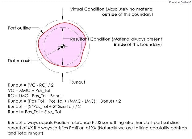
Here is my take on how "surface interpretations" of position and runout may look like:

Runout_vs_Position_vgcc1u.jpg


"For every expert there is an equal and opposite expert"
Arthur C. Clarke Profiles of the future
 
CH,

Before I dive too deep into this - as I was reading through the standard I noticed something. The surface interpretation (7.3.3.1.a and Fig 7-6) is only mentioned in regards to MMC (7.3.3.1) and LMC (7.3.5). Only in these two cases is there stated "the surface interpretation shall take precedence".

In the similar applicable section 7.3.2 regarding RFS positional tolerancing, there is no mention of the surface interpretation - only stating that "where applied to the positional tolerance of circular features of size, requires the axis or center point of each feature of size to be located within the specified positional tolerance regardless of the size of the feature". Could this mean that the example put forward by pylfrm is a valid interpretation for RFS position?
 
Chwz311,
Not so long ago there was a discussion on this forum about use of term "virtual condition" with RFS.
So, is RFS a boundary control?
It looks a little bit to me that first we stretch the rules and then are surprised by the results.
Still, I stand by my opinion that even if surface does not take the precedence, it is not legit to compare "surface vs axis" results.

"For every expert there is an equal and opposite expert"
Arthur C. Clarke Profiles of the future

 
I wonder how many people in the world when doing a radial tolerance stack-up that includes a runout tolerance, WOULD NOT assume that the maximum offset between axis of a feature controlled with that runout and the datum axis equals half of the runout tolerance? It is a rhetorical question, because this is what people would for sure do and this is what all stack-up books also tell us to do. And this is exactly where surface control (runout) gets translated into axis control.

Pylfrm's illustration geometrically (hence mathematically) shows this assumption doesn't always have to be true.
 
Here is a discussion where has been concluded (rightfully or not) that:

copy-paste from pmarc posted reply:

The fact is that in the draft of the new version of the standard there is clear statement in para. 5.8.2:
"The surface method shall take precedence where the tolerances are applied at MMC or LMC. [...] The surface method is not applicable where tolerances are applied RFS."

Therefore, in the new standard (that is about to release any day now) ASME Y14.5-2018 will show (hopefully) the statement indicated by pmarc above.


The value in virtual condition of an RFS feature has more to do with evaluating it as it interacts with mating parts than as a means of accepting the feature at inspection. The context of when the evaluation is meaningful is an important consideration.

AFAIK there's no linear transform between a surface interpretation and an axis interpretation for comparing position tolerance and total profile of a surface. Apparent connections seem based on surfaces that have very uniform curvature, eliminating a difficult to transform variable. The attraction of that assumption is that most machined round parts are, in fact, of very uniform curvature. It's rare to need to deal with a nominally round part where the curvature is allowed to change by 10%, at least on parts where either position or total runout of a surface are important.
 
CH (and all),

I remember that discussion, and I understand how some of those issues with interpretation of RFS/virtual condition could play into this topic.

That said, I've got a few questions for you (I apologize for their length in advance):

1) I'm not sure exactly what ASME means by "the tolerance in terms of the axis may not be exactly equivalent to the tolerance in terms of the surface" - could you provide some insight into this? In my mind the two cannot be truly "equivalent" since its a bit like comparing apples and oranges, one evaluates UAME axis deviations and one evaluates surface deviations. The way it reads in my mind is "if the axis interpretation falls outside the specified tolerance (fails for axis deviation) but the surface interpretation does not violate the virtual condition (passes for surface deviation), then surface interpretation takes precedence (the part passes inspection)". Is this a valid reading of the standard (ie: pass vs. fail for each)?

2) If you agree with my interpretation (1) above, then what would you say if the theoretical example in question (by pylfrm) was in regards to a feature which had a position tolerance applied of 10 but a total runout tolerance of 5? Would you agree that the measured position error is 9.544 as shown since it does not fail/fall outside of the specified position tolerance? If not, what do you believe would be the measured position error?

3) Taking a more practical approach to whether the surface interpretation makes sense for RFS, imagine a feature which looks like the one in Fig 7-6. First imagine that it is a feature with a tolerance applied at MMC and it is a clearance/through hole for a bolt - one can see how even though the axis of the UAME falls outside the specified tolerance, it still results in a perfectly usable part since the virtual condition is not violated and clearance to the bolt will still be provided in assembly. If the same feature has a tolerance applied at RFS because the intent is to mate in some way which would interact similarly to the UAME (ie: centering action of an expanding pin/mandrel or press fit) would not the deviation of the UAME axis be of critical importance over the surface interpretation?
 
chez311 said:
I'm not sure exactly what ASME means by "the tolerance in terms of the axis may not be exactly equivalent to the tolerance in terms of the surface"

I guess they meant something like this:

Axis_vs_Surface_xqvsji.png


This may (partially) answer your other questions

"For every expert there is an equal and opposite expert"
Arthur C. Clarke Profiles of the future
 
CH,

Unfortunately that doesn't really help me understand much more than Y14.5 already lays out. Maybe I'm missing something, I know I might not have as tight a grasp on the concepts as others here.

To further clarify what I was asking in my question (1), it seemed to me that by what is meant by "equivalent" is really whether the interpretations are in agreement, as in the feature would pass by both interpretations or fail by both interpretations. This is because I do not understand how the magnitude of a surface deviation could be directly compared to the magnitude of an axis deviation and then considered mathematically equivalent. It is only when the two interpretations are no longer in agreement, and the feature passes by one and fails by another that the surface interpretation can be considered to take precedence.
 
I would say they are NEVER in agreement, except the simplest cases of perfect form and orientation.
But in this case there wouldn't be difference between position and runout anyway.

"For every expert there is an equal and opposite expert"
Arthur C. Clarke Profiles of the future

 
CH,

By agreement I didn't mean "identical" or the same - I just meant that the feature would either pass BOTH or fail BOTH, I don't think that requires "the simplest cases of perfect form and orientation" to pass/fail both simultaneously. Unless someone can show me a way to mathematically compare surface deviation to axis deviation I am going to take my statement an accurate interpretation of what is meant by "equivalent".

Do you by chance have any thoughts on my questions (2) and (3)? I realize they were lengthy and I apologize but the excerpt you provided did not help me answer these questions.
 
I did not mean "identical" either.
I meant they will never measure exactly the same, so passing and failing both all the same time is not an option.
Wasn't the picture I provided compare surface deviation to axis deviation? If they can be so far away even in one example, they are not "equivalent" - that's your math.
About 2) and 3) - I will try to come up with some convincing graphics, but no promise (will need time)

"For every expert there is an equal and opposite expert"
Arthur C. Clarke Profiles of the future

 
CH said:
I meant they will never measure exactly the same
I agree - although as I said for a different reason because I don't know how one compares axis deviation to surface deviation (volume/area? max distance? min distance? average deviation? would any of these comparisons even be valid?).

CH said:
so passing and failing both all the same time is not an option
I don't know if I understand this. Why don't you think that a feature could pass both or fail both interpretations? Surface and axis measurements wouldn't have to be identical to still pass/fail both..

CH said:
About 2) and 3) - I will try to come up with some convincing graphics, but no promise (will need time)
Okay - sounds good, I'm interested as to your take on them. If you don't get to it I understand, just always trying to expand my knowledge and understand all viewpoints.
 
Oh, sorry. It is possible that both will pass or both will fail. It's just one passing doesn't mean the other should.
Or should I say they will not pass/fail at exactly the same moment/measurement.

Your questions,

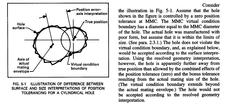
1)"if the axis interpretation falls outside the specified tolerance (fails for axis deviation) but the surface interpretation does not violate the virtual condition (passes for surface deviation), then surface interpretation takes precedence (the part passes inspection)". Is this a valid reading of the standard?"
Fig. 7-6 says exactly so:

Capture_uw37vs.png


2)Neither OP, pmarc, or pylfrm specified if position is RFS, so the same common rule applies: surface beats axis. Example is not legit.

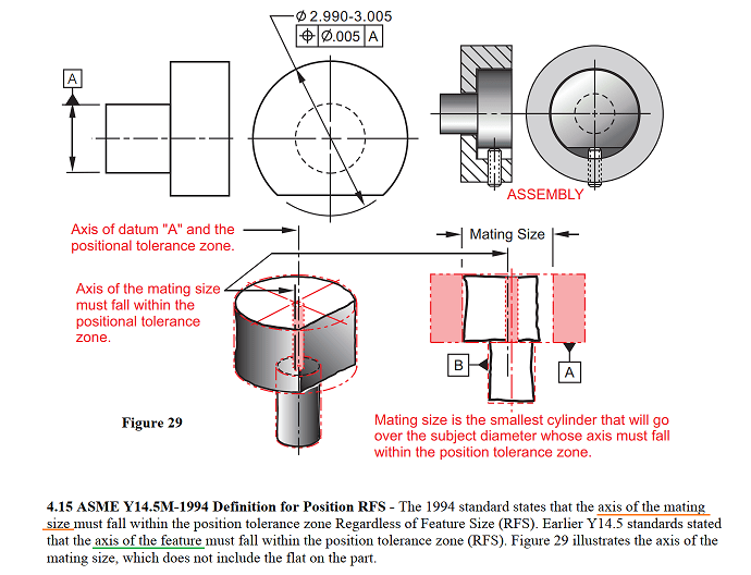
3) When we have RFS explicitly specified, then yes, UAME definition may be critical. RFS is legitimate control when part is functionally clamped / "pushed" against some kind of "mating diameter", also parts that are not all-together round, like the following illustration shows. What will happen to runout in application like this - I am not sure.

Axis_RFS_shmiwk.png


"For every expert there is an equal and opposite expert"
Arthur C. Clarke Profiles of the future
 
CH said:
2)Neither OP, pmarc, or pylfrm specified if position is RFS, so the same common rule applies: surface beats axis. Example is not legit.
I was asking a hypothetical that would have allowed the feature to pass under both interpretations (tolerance size of 10 so that an axis interpretation with position error 9.544 was within tolerance). There are many instances where one might want to determine the exact error/deviation instead of just determining pass/fail - I was trying to ask what you believe the magnitude of position error to be, I (and others) say it is 9.544 under the axis interpretation. Can the surface (or any other) interpretation provide a discrete value for position error? I'm not even sure how it being legitimate or not plays into it, it is a feature with geometry - if you boil it down, the question was really simply "what do you believe the position error is?" Or in fact if we want to take into account material condition, and since its a hypothetical anyway, it could be "what do you believe the position error is if it is at RFS? what do you believe the position error is if it is at MMC?".


CH said:
3) When we have RFS explicitly specified, then yes, UAME definition may be critical.
Then we agree on that point. Seems to me that everything points to the fact that for RFS, the axis interpretation is the only one that should be used unless otherwise specified.
 
Although not explicitly stated, RFS is certainly what pmarc had in mind with the reference to my image.


ASME Y14.5-2009 para. 7.2 said:
A positional tolerance defines either of the following:
(a) a zone within which the center, axis, or center plane of a feature of size is permitted to vary from a true (theoretically exact) position
(b) (where specified on an MMC or LMC basis) a boundary, defined as the virtual condition, located at the true (theoretically exact) position, that may not be violated by the surface or surfaces of the considered feature of size.

This seems pretty clear to me. Nonetheless, it's interesting to evaluate the same example using the surface interpretation for RFS position tolerances defined by ASME Y14.5.1M-1994. That calculation results in an actual value of 100.00 - 99.544 = 0.456 diameter.

A size tolerance must be assumed to determine actual values for MMC and LMC position tolerances. A size tolerance of 95 +/- 5 yields actual values of 0 for both MMC and LMC, while a size tolerance of 97.5 +/- 2.5 yields actual values of 0 for MMC and 5 for LMC.


pylfrm
 
pylfrm,

I meant to thank you for your confirmation on the 180 degree opposed points, it got a bit lost in the shuffle, but it helped confirm that I understood your reasoning. I appreciate it.

In regards to the surface interpretation calculations you provided, as per usual I find the math standard a bit difficult to follow. Is there any chance you could provide a bit of explanation on your calculations and what exactly they mean? For example for RFS what exactly a 0.456 diameter means in terms of deviation of the surface?
 
chez311,

Per ASME Y14.5.1M-1994, the actual value of RFS position deviation is equal to the size difference between the RAME (using the appropriate DRF) and the UAME. This can be concluded from paras. 5.2 and 5.2.1 along with Tables 5-1 and 5-2.

Perhaps that's not much of an explanation, but I imagine it might be sufficient. Let me know what you think.


pylfrm
 
pylfrm,

Sorry, I'm a little confused. For example for RFS, table 5-2 suggests the size of the surface interpretation of the position tolerance zone involves the radius of the AME (actually says nothing about UAME or RAME as the variable r_AM is just described as "actual mating size") and half the specified position tolerance.

Additionally, if it were as you suggest (size difference between UAME and RAME) wouldn't that be zero in this case? Unless there is orientation error, which I do not think we were assuming any with this simplified 2D case, the UAME and RAME would be identical (99.544) - right? I may well be missing something, this stuff just isn't adding up for me.
 
Status
Not open for further replies.

Part and Inventory Search

Sponsor