Continue to Site

Eng-Tips is the largest engineering community on the Internet

Intelligent Work Forums for Engineering Professionals

  • Congratulations KootK on being selected by the Eng-Tips community for having the most helpful posts in the forums last week. Way to Go!

Datum ref frame B & C were both center plane, is that correct?

Bryan.mys

Mechanical
Aug 1, 2024
4
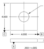
I came across a post about gd&t with this drawing
1730972543401.png
I am struggle to make sense of it.

Datum plane B is created by 2 faces while perpendicular to Datum plane A.
Datum plane B already control the 2nd translational and 3rd rotational freedom.
Datum plane C is supposed to be perpendicular to Datum plane A and B.
If datum plane C is created by 2 faces, will that violate perpendicularity with A or B?
Or datum plane C is created by the center point of a line created by 2 points on each face while perpendicular to Datum plane A and Datum plane B.
 
Last edited:
Replies continue below

Recommended for you

Datum plane B is created by 2 faces while perpendicular to Datum plane A.
-Yes
Datum plane B already control the 2nd translational and 3rd rotational freedom.
-Yes
Datum plane C is supposed to be perpendicular to Datum plane A and B.
-Yes
If datum plane C is created by 2 faces, will that violate perpendicularity with A or B?
-No
Or datum plane C is created by the center point of a line created by 2 points on each face while perpendicular to Datum plane A and Datum plane B.
-It could be a single point of contact on each opposing face.
 
Hi, Bryan.mys:

There is something called "datum precedence".

Your datum feature A control 3 degrees of freedom;
Your datum feature B control 2 degrees of freedom;
Your datum feature C ONLY control 1 degree of freedom.

Your datum plane C is perfectly (or "BASIC" in GD&T) perpendicular to both datum planes "A" and "B".

Datum plane C is not what is in your mind. Datum plane C is a plane that is perpendicular to datum plane "A" and "B" AND is best fit to center of feature of size (with the vertical dimensions 4.000). I hope this makes sense to you.

Best regards,

Alex
 
Last edited:
Hi, 3DDave:

I just noticed your comments after I posted mine. Your statements are accurate except the following:

"Or datum plane C is created by the center point of a line created by 2 points on each face while perpendicular to Datum plane A and Datum plane B."

Datum plane C is perpendicular to datum plane A and datum plane B. We agree on this.

Datum plane C is a plane that is best fitted to a bunch of points of cloud (technically they are called "derived medium points") which are medium points of feature of size C.

In CMM, you measure a bunch of points on one surface of feature of size C. Then you measure the same number of points on the other surface. These two sets of measurement points are used to calculate "derived medium point". Datum plane C is best fitted to these "derived medium points while maintaining perpendicularity to datum A and B.

Best regards,

Alex
 
That would be "median" not medium and, no, that isn't true. If it is called "medium points" in the software then that seems like poorly designed software.

If they are using a best fit then that is a terrible strategy. The planes that close onto the datum C datum feature stop at the highest point(s); finding one high point ends the search. To do least squares simply allows the datum to be derived from some place inside the solid part.
 
That is how the algorithm works on CMM machine. Your CMM stylus touch a bunch of points on one side. And it touches corresponding points on the other side. The datum plane C is established based on those "median" points using least squared error method.

Best regards,

Alex
 
Hi, 3DDave:

You may not like this explanation below. But please take a look at it. This algorithm is different depending on whether the derived mediam plane is primary, secondary, or tertiary datum.

"
Yes, Hexagon's Coordinate Measuring Machine (CMM) software does have functionality to measure a derived median plane for features of size, typically in line with Geometric Dimensioning and Tolerancing (GD&T) standards.

The derived median plane is used to represent the median (center) plane of a feature of size (like a slot or a tab), which is crucial for accurate GD&T evaluation. Hexagon CMM software, including PC-DMIS and QUINDOS, provides options to calculate and measure median planes for various features. This feature typically involves:

  1. Defining the Feature of Size: The software can identify the width or thickness of the feature (e.g., a slot or tab).
  2. Calculating the Median Plane: Based on the opposing surfaces of the feature, the software determines the midplane by averaging the points on the two surfaces.
  3. Displaying and Reporting: The derived median plane can then be reported, and its position and orientation relative to other features can be measured.
"
 
The datum is not determined from the derived median plane. That plane serves solely to function in the event that straightness or flatness is invoked.

The Actual Mating Envelope is required when a feature of size is referenced as a datum feature or when used to determine the position.
 
To the OP.... are we to assume that the question is about a callout that references A, B, and C in that order?
If not, then most of the replies above won't apply.
 
The question is about a callout that references A, B, and C in that order
To the OP.... are we to assume that the question is about a callout that references A, B, and C in that order?
If not, then most of the replies above won't apply.
 
Thanks guys, things are clearing up a lot.

While you guys are talking about using CMM to get center plane form 2 surfaces. I was wondering, will the Datum plane C be different when using CMM vs using Angle blocks/gauge blocks?
 
A fixture for datum simulation in this case would include:
1. A flat planar surface to simulate datum plane A.
2. A pair of vise jaws perpendicular to the flat surface to simulate datum B (the datum would be their center plane).
3.Another pair of vise jaws perpendicular to the flat surface and the 'B' jaws to simulate datum C (the datum would be their center plane).
 
Agree with Burunduk. There is no FCF (feature control frame) that shows how datum feature A, B, and C are used.
 
I agree with Burunduk. Don't forget that Datum are mathematical models. The way I can explain it is with cad. imagine scaning a very crooket part and importing it in your favorite cad. lets assume that the order of precedence is A then B and then C.

For datum A
You would create a plane (P1) passing though the 3 highest peaks of face A. that plane becomes DATUM A.

For datum B
You would create two parallel planes (P2 and P3) perpendicular to DATUM A, 4.005 apart, on each side of the horizontal 4 in dimension. you would decrease the distance between these two planes until the part is locked in place. Once locked, create a plane (P4) at the center of the two previouse planes (P2 and P3). That plane (P4) is Datum B.

note that P2 and P3 only need to be parallel to datum A, so they can rotate 360° until they make the best possible contact with the part, as long as they remain perpendicular to datum A.

For Datum C

create againt two parallel planes (P5 and P6) 4.005 appart, this time perpendicular to DATUM A and DATUM B. Unlike the previous case, these two parallel planes cannot rotate at all, since there are perpendicular to B. (and A obviously). they can only slide toward each other, which you will do until it locks the part. Once locked, create a plane (P7) at the center of the two previouse planes (P5 and P6). P7 is now datum C.

In short, if the produced part was shaped like a diamond, P2 and P3 would touch the two parallel faces while P5 and P6 would only touch the points of the diamond.

Hope it makes some sence.

Since english is my 3rd language, I hope it's not confusing.
 
supergee's explanation is detailed and correct.
3DDave's first reply is extremely concise version and that's why he said as below.

" Or datum plane C is created by the center point of a line created by 2 points on each face while perpendicular to Datum plane A and Datum plane B.
-It could be a single point of contact on each opposing face. "
 

Part and Inventory Search

Sponsor